Advertisement
Table of Contents
- 1 Table of Contents
- 2 Warning Decal Placement
- 3 Important Precautions
- 4 Before You Begin
- 5 Part Identification Chart
- 6 Assembly
- 7 How to Use the Treadmill
- 8 Fcc Information
- 9 How to Fold and Move the Treadmill
- 10 Maintenance and Troubleshooting
- 11 Exercise Guidelines
- 12 Part List
- 13 Exploded Drawing
- 14 Ordering Replacement Parts
- 15 Limited Warranty
- Download this manual
proform.com
Model No. PFTL69619.0
Serial No.
Write the serial number in the space
above for reference.
Serial Number
Decal
ACTIVATE YOUR
WARRANTY
To register your product and
activate your warranty today, go
to my.proform.com.
CUSTOMER CARE
For service at any time, go to
proformservice.com.
Or call 1-866-362-4490
Mon.–Fri. 6 a.m.–6 p.m. MT
Sat. 8 a.m.–12 p.m. MT
Please do not contact the store.
CAUTION
Read all precautions and
instructions in this manual before
using this equipment. Save this
manual for future reference.
USER'S MANUAL
Advertisement
Table of Contents

Related Manuals for Pro-Form 965 CT


Summary of Contents for Pro-Form 965 CT
- Page 1 proform.com Model No. PFTL69619.0 USER’S MANUAL Serial No. Write the serial number in the space above for reference. Serial Number Decal ACTIVATE YOUR WARRANTY To register your product and activate your warranty today, go to my.proform.com. CUSTOMER CARE For service at any time, go to proformservice.com.
-
Page 2: Table Of Contents
TABLE OF CONTENTS WARNING DECAL PLACEMENT ............. . . 2 IMPORTANT PRECAUTIONS . -
Page 3: Important Precautions
IMPORTANT PRECAUTIONS WARNING: To reduce the risk of burns, fire, electric shock, or injury to persons, read all important precautions and instructions in this manual and all warnings on your treadmill before using your treadmill. ICON assumes no responsibility for personal injury or property damage sus- tained by or through the use of this product. - Page 4 19. Always stand on the foot rails when starting 26. When folding or moving the treadmill, make or stopping the walking belt. Always hold the sure that the storage latch is holding the handrails while using the treadmill. frame securely in the storage position. Do not operate the treadmill while it is folded.
- Page 5 STANDARD SERVICE PLANS...
-
Page 6: Before You Begin
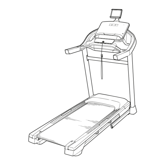
Thank you for selecting the revolutionary PROFORM ® reading this manual, please see the front cover of this 965 CT treadmill. The 965 CT treadmill offers an manual. To help us assist you, please note the product impressive selection of features designed to make your model number and serial number before contacting us. -
Page 7: Part Identification Chart
PART IDENTIFICATION CHART Use the drawings below to identify small parts used for assembly. The number in parentheses below each draw- ing is the key number of the part, from the PART LIST near the end of this manual. The number following the key number is the quantity used for assembly. -
Page 8: Assembly
ASSEMBLY • To hire an authorized service technician to • Left parts are marked “L” or “Left” and right parts assemble the treadmill, call 1-800-445-2480 are marked “R” or “Right.” • Assembly requires two persons. • To identify small parts, see page 7. •... - Page 9 2. Make sure that the power cord is unplugged. Remove the tie securing the Upright Wire (81) to the front of the Base (94). Next, identify the Right Upright (90). Have a sec- ond person hold the Right Upright near the Base (94).
- Page 10 4. Hold the Right Upright (90) against the Base (94). Make sure not to pinch the Upright Wire (81). Next, hold a Wheel (97) inside the Base (94), and insert a 3/8" x 1 3/4" Screw (62) with a 3/8" Star Washer (13) through the Base and the Wheel as shown;...
- Page 11 6. Identify the Left and Right Handrails (86, 87). Attach the Right Handrail (87) to the Right Upright (90) with two 5/16" x 2 1/2" Screws (28) and two 5/16" Star Washers (11) in the location shown; start both Screws before tightening them.
- Page 12 8. With the help of a second person, hold the console assembly (F) near the Right Upright (90). Next, insert the Upright Wire (81) through the indicated looped tie (G). Note: the console assembly (F) may have two ties. If so, insert the Upright Wire through both.
- Page 13 11. Identify the Right Handrail Cover (92). Set the Right Handrail Cover on the Right Handrail (87). Start two #8 x 3/4" Truss Head Screws (23) into the bottom of the Handrail Cover; do not fully tighten the Truss Head Screws. Next, slide the Right Handrail Cover (92) for- ward until it rests against the console assembly (F).
- Page 14 13. Note: If the treadmill is assembled on a smooth surface, it may roll forward during this step. Raise the Frame (56) to the upright position. IMPORTANT: Do not raise the Frame past the vertical position. Have a second person hold the Frame until step 15 is completed.
- Page 15 15. Remove the 5/16" Nut (12) and the 5/16" x 2 1/4" Bolt (3) from the bracket on the Latch Crossbar (38). 12 L Align the upper end of the Storage Latch (53) with the bracket on the Latch Crossbar (38), and insert the 5/16"...
- Page 16 17. Press the two tabs (not shown) on the Tablet Holder (41) into the slots (M) in the console assembly (F). Then, attach the Tablet Holder (41) with four M4 x 16mm Machine Screws (26). Start all four Machine Screws before tightening them. Do not overtighten the Machine Screws.
-
Page 17: How To Use The Treadmill
HOW TO USE THE TREADMILL HOW TO CONNECT THE POWER CORD more amps. To avoid overloading the circuit, do not plug other electrical devices, except for low- Use a Surge Suppressor power devices such as cell phone chargers, into the surge suppressor or into an outlet on the same Your treadmill, like other electronic equipment, can be circuit. - Page 18 CONSOLE DIAGRAM FEATURES OF THE CONSOLE You can even listen to your favorite workout music or audio books with the console’s sound system while you IMPORTANT: To activate your console and begin exercise. using its exclusive features, see assembly step 18 on page 16.
- Page 19 HOW TO TURN ON THE POWER HOW TO USE THE MANUAL MODE IMPORTANT: If the treadmill has been exposed to 1. Insert the key into the console. cold temperatures, allow it to warm to room tem- perature before you turn on the power. If you do See HOW TO TURN ON THE POWER at the left.
- Page 20 4. Change the incline of the treadmill as desired. To reset the displays, press the Stop button repeatedly. To change the incline of the treadmill, press the Incline increase and decrease buttons or one of the 6. Measure your heart rate if desired. numbered incline buttons.
- Page 21 7. When you are fi nished exercising, remove the Each workout is divided into segments. One speed key from the console. setting and one incline setting are programmed for each segment. Note: The same speed setting and/ Step onto the foot rails, press the Stop button, and or incline setting may be programmed for consecu- adjust the incline of the treadmill to zero.
- Page 22 HOW TO CONNECT YOUR TABLET TO THE 4. Record and track your workout information. CONSOLE Follow the instructions in the iFit–Smart Cardio The console supports Bluetooth connections to tab- Equipment app to record and track your workout lets via the iFit–Smart Cardio Equipment app and to information.
- Page 23 HOW TO CONNECT YOUR HEART RATE MONITOR THE SETTINGS MODE TO THE CONSOLE The console features a settings mode that keeps track The console is compatible with all Bluetooth Smart of treadmill usage information and allows you to select heart rate monitors. a unit of measurement for the console.
-
Page 24: Fcc Information
HOW TO USE THE TABLET HOLDER IMPORTANT: The tablet holder (E) is designed for use with most full-size tablets. Do not place any other electronic device or object in the tablet holder. To insert a tablet into the tablet holder (E), set the bot- tom edge of the tablet in the tray. -
Page 25: How To Fold And Move The Treadmill
HOW TO FOLD AND MOVE THE TREADMILL HOW TO FOLD THE TREADMILL HOW TO MOVE THE TREADMILL To avoid damaging the treadmill, adjust the incline Before moving the treadmill, fold it as described at the to zero before you fold the treadmill. Then, remove left. -
Page 26: Maintenance And Troubleshooting
MAINTENANCE AND TROUBLESHOOTING MAINTENANCE c. Check the power switch located on the treadmill frame near the power cord. If the switch protrudes Regular maintenance is important for optimal as shown, the switch has tripped (A). To reset the performance and to reduce wear. Inspect and prop- power switch, wait fi... - Page 27 SYMPTOM: The incline of the treadmill does not c. Your treadmill features a walking belt coated with change correctly high-performance lubricant. IMPORTANT: Never apply silicone spray or other substances to a. Hold down the Stop button, insert the key into the the walking belt or the walking platform unless console, and then release the Stop button.
- Page 28 b. If the walking belt slips when walked on, fi rst SYMPTOM: The tablet holder does not stay in remove the key and UNPLUG THE POWER place CORD. Using the hex key, turn both idler roller screws clockwise, 1/4 of a turn. When the walking a.
-
Page 29: Exercise Guidelines
EXERCISE GUIDELINES Burning Fat—To burn fat effectively, you must exer- WARNING: cise at a low intensity level for a sustained period of Before beginning this time. During the first few minutes of exercise, your or any exercise program, consult your physi- body uses carbohydrate calories for energy. -
Page 30: Part List
PART LIST Model No. PFTL69619.0 R0819A Key No. Qty. Description Key No. Qty. Description #8 x 1/2" Screw Platform Cushion #8 x 3/4" Screw M5 Flat Washers 5/16" x 2 1/4" Bolt Storage Latch 1/4" x 1/2" Screw Drive Motor #10 Star Washer Motor Belt 5/16"... - Page 31 Key No. Qty. Description Key No. Qty. Description Base Pad Electronics Bracket 1/4" x 1 1/4" Screw 9/32" Plastic Bushing 1/4" Nut – User’s Manual Note: Specifi cations are subject to change without notice. For information about ordering replacement parts, see the back cover of this manual.
-
Page 32: Exploded Drawing
EXPLODED DRAWING A Model No. PFTL69619.0 R0819A... - Page 33 EXPLODED DRAWING B Model No. PFTL69619.0 R0819A...
- Page 34 EXPLODED DRAWING C Model No. PFTL69619.0 R0819A 62 13 14 13...
- Page 35 EXPLODED DRAWING D Model No. PFTL69619.0 R0819A...
-
Page 36: Ordering Replacement Parts
ORDERING REPLACEMENT PARTS To order replacement parts, please see the front cover of this manual. To help us assist you, be prepared to provide the following information when contacting us: • the model number and serial number of the product (see the front cover of this manual) •...
Need help?
Do you have a question about the 965 CT and is the answer not in the manual?
Questions and answers