Table of Contents
Advertisement
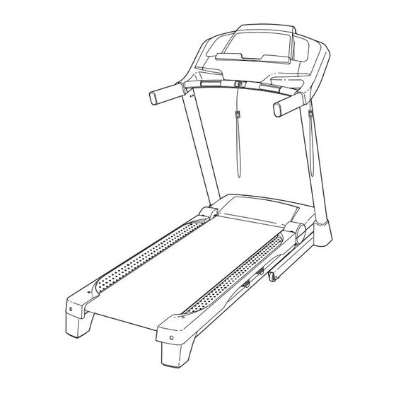
Model No. PETL99711.0
Serial No.
Write the serial number in the space
above for reference.
Serial Number
Decal
QUESTIONS?
If you have questions, or if there are
missing parts, please contact us:
UK
Call: 08457 089 009
From Ireland: 053 92 36102
Website: www.iconsupport.eu
E-mail: csuk@iconeurope.com
Write:
ICON Health & Fitness, Ltd.
c/o HI Group PLC
Express Way
Whitwood, West Yorkshire
WF10 5QJ, UK
AUSTRALIA
Call: 1-800-237-173
E-mail:
australiacc@iconfitness.com
CAUTION
Read all precautions and instruc-
tions in this manual before using
this equipment. Save this manual
for future reference.
USERʼS MANUAL
Advertisement
Table of Contents

Subscribe to Our Youtube Channel
Related Manuals for Pro-Form PERFORMANCE 950


Summary of Contents for Pro-Form PERFORMANCE 950
- Page 1 USERʼS MANUAL Model No. PETL99711.0 Serial No. Write the serial number in the space above for reference. Serial Number Decal QUESTIONS? If you have questions, or if there are missing parts, please contact us: Call: 08457 089 009 From Ireland: 053 92 36102 Website: www.iconsupport.eu E-mail: csuk@iconeurope.com Write:...
-
Page 2: Table Of Contents
TABLE OF CONTENTS WARNING DECAL PLACEMENT ............. .2 IMPORTANT PRECAUTIONS . -
Page 3: Important Precautions
IMPORTANT PRECAUTIONS WARNING: To reduce the risk of serious injury, read all important precautions and in- structions in this manual and all warnings on your treadmill before using your treadmill. ICON as- sumes no responsibility for personal injury or property damage sustained by or through the use of this product. - Page 4 DANGER: 20. Do not attempt to raise, lower, or move the Always unplug the power treadmill until it is properly assembled. (See cord immediately after use, before cleaning the ASSEMBLY on page 7, and HOW TO FOLD treadmill, and before performing the mainte- AND MOVE THE TREADMILL on page 24.) nance and adjustment procedures described in You must be able to safely lift 45 lbs.
-
Page 5: Before You Begin
Thank you for selecting the revolutionary PROFORM ing this manual, please see the front cover of this man- ® PERFORMANCE 950 treadmill. The PERFORMANCE ual. To help us assist you, please note the product 950 treadmill offers an impressive selection of features model number and serial number before contacting us. -
Page 6: Part Identification Chart
PART IDENTIFICATION CHART Use the drawings below to identify small parts used for assembly. The number in parentheses below each draw- ing is the key number of the part, from the PART LIST near the end of this manual. The number following the key number is the quantity used for assembly. -
Page 7: Assembly
ASSEMBLY • Assembly requires two persons. • Assembly requires the following tools: • Place all parts in a cleared area and remove the the included hex keys packing materials. Do not dispose of the packing materials until you finish assembly. one adjustable wrench •... - Page 8 2. With the help of a second person, carefully tip the treadmill onto its left side. Partially fold the Hole Frame (55) so that the treadmill is more stable; do not fully fold the Frame yet. Cut the shipping tie securing the Upright Wire (87) to the Base (95).
-
Page 9: Wire (87). Insert Two 3/8" X 4" Screws (7) With
4. Identify the Right Upright (85), which is marked “Right.” Hold the Right Upright near the Base (95) as shown. See the inset drawing. Tie the wire tie in the Right Upright (85) securely around the end of Wire Tie the Upright Wire (87). - Page 10 6. With the help of a second person, carefully tip the treadmill onto its right side. Partially fold the Frame (55) so that the treadmill is more stable; do not fully fold the Frame yet. Attach a Wheel (96) to the Base (95) with a 3/8" x 2"...
- Page 11 8. Identify the Right Base Cover (91) and the Left Base Cover (88). Slide the Right Base Cover onto the Right Upright (85). Slide the Left Base Cover onto the Left Upright (84). 9. Hold the Right Handrail (83) near the Right Upright (85).
-
Page 12: The Upright Wire (87)
11. IMPORTANT: To avoid damaging the Crossbar (107), do not use power tools and do not overtighten the #10 x 3/4" Screws (2). Orient the Crossbar (107) as shown. Attach the Crossbar to the Handrails (82, 83) with four #10 x 3/4"... - Page 13 13. Set the console assembly on the Left Handrail (82) and the Right Handrail (83). Be careful not Console to pinch any wires. Insert the excess Upright Assembly Wire (not shown) into the Right Handrail. Attach the console assembly with six #8 x 3/4" Screws (1) and four 1/4"...
-
Page 14: The Chest Heart Rate Monitor
THE CHEST HEART RATE MONITOR THE OPTIONAL CHEST HEART RATE MONITOR Whether your goal is to burn fat or to strengthen your cardiovascular system, the key to achieving the best results is to maintain the proper heart rate during your workouts. -
Page 15: Operation And Adjustment
OPERATION AND ADJUSTMENT HOW TO PLUG IN THE POWER CORD Follow the steps below to plug in the power cord. This product must be earthed. If it should malfunc- 1. Plug the indicated end of the power cord into the tion or break down, earthing provides a path of least socket on the treadmill. - Page 16 CONSOLE DIAGRAM FEATURES OF THE CONSOLE your progress toward your fitness goals. To purchase a SYNC at any time, call the telephone number on the front cover of this manual. The treadmill console offers an impressive array of features designed to make your workouts more effec- tive and enjoyable.
- Page 17 HOW TO TURN ON THE POWER HOW TO USE THE MANUAL MODE IMPORTANT: If the treadmill has been exposed to 1. Insert the key into the console. cold temperatures, allow it to warm to room tem- perature before you turn on the power. If you do See HOW TO TURN ON THE POWER at the left.
- Page 18 4. Change the incline of the treadmill as desired. The Distance/Speed display—This display To change the incline of the treadmill, press the can show the distance Incline increase or decrease button or one of the that you have walked or incline buttons numbered 0 through 10.
- Page 19 6. Measure your heart rate if desired. 7. When you are finished exercising, remove the key from the console. Note: If you use the handgrip heart rate monitor and the chest heart rate monitor at the same Step onto the foot rails, press the Stop button, and time, the console will not display your heart adjust the incline of the treadmill to the lowest rate accurately.
-
Page 20: How To Use Onboard Workout
HOW TO USE AN ONBOARD WORKOUT the displays for a few seconds and the treadmill will automatically adjust to the new speed and/or in- 1. Insert the key into the console. cline setting. See HOW TO TURN ON THE POWER on page 17. The workout will continue in this way until the last segment of the profile flashes in the display and the 2. - Page 21 HOW TO USE AN IFIT LIVE WORKOUT Compete button to compete in a race that you have previously scheduled. For more information about the iFit Live workouts, please see Note: To use an iFit Live workout, you must have an www.iFit.com.
- Page 22 HOW TO USE THE PROFORM SYNC HOW TO USE THE STEREO SOUND SYSTEM The optional PROFORM SYNC enables you to record This treadmill has been designed specifically to work your treadmill workout results on your iPod (not in- with iPod and has been certified by the developer to ®...
- Page 23 THE INFORMATION MODE ON will appear in the center display. To turn on or turn off the demo mode, press the Enter button or The console features an information mode that keeps the Speed decrease button. track of treadmill information and allows you to person- 3.
-
Page 24: How To Fold And Move The Treadmill
HOW TO FOLD AND MOVE THE TREADMILL HOW TO FOLD THE TREADMILL HOW TO MOVE THE TREADMILL To avoid damaging the treadmill, adjust the incline Before moving the treadmill, fold it as described at the to the lowest position before you fold the treadmill. left. -
Page 25: Troubleshooting
TROUBLESHOOTING Most treadmill problems can be solved by following SYMPTOM: The console displays remain lit when the simple steps below. Find the symptom that you remove the key from the console applies, and follow the steps listed. If further assis- tance is needed, see the front cover of this manual. - Page 26 SYMPTOM: The walking belt slows when walked on Next, remove the three #8 x 3/4" Screws (1), and carefully pivot the Motor Hood (62) off. a. If an extension cord is needed, use only a 3-con- ductor, 14-gauge (1 mm ) cord that is no longer than 5 ft.
- Page 27 SYMPTOM: The walking belt is off-center or slips b. If the walking belt slips when walked on, first re- when walked on move the key and UNPLUG THE POWER CORD. Using the hex key, turn both idler roller screws a. If the walking belt is off-center, first remove the clockwise, 1/4 of a turn.
-
Page 28: Exercise Guidelines
EXERCISE GUIDELINES WARNING: Burning Fat—To burn fat effectively, you must exer- cise at a low intensity level for a sustained period of Before beginning this time. During the first few minutes of exercise, your or any exercise program, consult your physi- body uses carbohydrate calories for energy. - Page 29 SUGGESTED STRETCHES The correct form for several basic stretches is shown at the right. Move slowly as you stretch—never bounce. 1. Toe Touch Stretch Stand with your knees bent slightly and slowly bend forward from your hips. Allow your back and shoulders to relax as you reach down toward your toes as far as possible.
-
Page 30: Part List
PART LIST Model No. PETL99711.0 R0611A Key No. Qty. Description Key No. Qty. Description #8 x 3/4" Screw Storage Latch #10 x 3/4" Screw Console Ground Wire Inner Cushion #8 x 1" Screw 5/16" x 1" Bolt Right Foot Rail #8 x 1"... - Page 31 Key No. Qty. Description Key No. Qty. Description Console Right Tray Console Frame Motor Bushing Left Tray Motor Isolator #8 x 3/4" Truss Head Screw Electronics Bracket Console Clamp Filter Console Base – Userʼs Manual Crossbar Note: Specifications are subject to change without notice. For information about ordering replacement parts, see the back cover of this manual.
-
Page 32: Exploded Drawing
EXPLODED DRAWING A Model No. PETL99711.0 R0611A... - Page 33 EXPLODED DRAWING B Model No. PETL99711.0 R0611A...
- Page 34 EXPLODED DRAWING C Model No. PETL99711.0 R0611A...
- Page 35 EXPLODED DRAWING D Model No. PETL99711.0 R0611A...
-
Page 36: Ordering Replacement Parts
ORDERING REPLACEMENT PARTS To order replacement parts, please see the front cover of this manual. To help us assist you, be prepared to pro- vide the following information when contacting us: • the model number and serial number of the product (see the front cover of this manual) •...
Need help?
Do you have a question about the PERFORMANCE 950 and is the answer not in the manual?
Questions and answers