Table of Contents
Advertisement
www.proform.com
Model No. PFTL99612.0
Serial No.
Write the serial number in the space
above for reference.
Serial Number
Decal
QUESTIONS?
If you have questions, or if parts
are damaged or missing, DO NOT
CONTACT THE STORE; please
contact Customer Care.
IMPORTANT: Please register this
product (see the limited warranty
on the back cover of this manual)
before contacting Customer Care.
CALL TOLL-FREE:
1-888-533-1333
Mon.–Fri. 6 a.m.–6 p.m. MT
Sat. 8 a.m.–4 p.m. MT
ON THE WEB:
www.proformservice.com
CAUTION
Read all precautions and instruc-
tions in this manual before using
this equipment. Save this manual
for future reference.
USER'S MANUAL
Advertisement
Table of Contents

Related Manuals for Pro-Form PFTL99612.0


Summary of Contents for Pro-Form PFTL99612.0
- Page 1 Model No. PFTL99612.0 Serial No. USER’S MANUAL Write the serial number in the space above for reference. Serial Number Decal QUESTIONS? If you have questions, or if parts are damaged or missing, DO NOT CONTACT THE STORE; please contact Customer Care.
-
Page 2: Table Of Contents
TABLE OF CONTENTS WARNING DECAL PLACEMENT ............. . .2 IMPORTANT PRECAUTIONS . -
Page 3: Important Precautions
IMPORTANT PRECAUTIONS WARNING: To reduce the risk of burns, fire, electric shock, or injury to persons, read all important precautions and instructions in this manual and all warnings on your treadmill before using your treadmill. ICON assumes no responsibility for personal injury or property damage sus- tained by or through the use of this product. - Page 4 20. The heart rate monitor is not a medical 24. Do not change the incline of the treadmill by device. Various factors, including the user’s placing objects under the treadmill. movement, may affect the accuracy of heart rate readings. The heart rate monitor is 25.
-
Page 5: Before You Begin
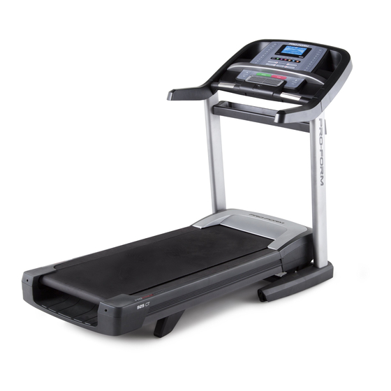
BEFORE YOU BEGIN Thank you for selecting the revolutionary PROFORM reading this manual, please see the front cover of this ® 925 CT treadmill. The 925 CT treadmill offers an manual. To help us assist you, please note the product impressive selection of features designed to make your model number and serial number before contacting us. -
Page 6: Part Identification Chart
PART IDENTIFICATION CHART Use the drawings below to identify small parts used for assembly. The number in parentheses below each draw- ing is the key number of the part, from the PART LIST near the end of this manual. The number following the key number is the quantity used for assembly. -
Page 7: Assembly
ASSEMBLY • To hire an authorized service technician • To identify small parts, see page 6. to assemble your exercise equipment, call 1-800-445-2480. • Assembly requires the following tools: the included hex keys • Assembly requires two persons. one adjustable wrench •... -
Page 8: A) Through The Indicated Hole In The Base (91
2. Pull the Upright Wire (77) and the ground wire (A) through the indicated hole in the Base (91). Attach the ground wire (A) to the Base (91) with a #8 x 1/2" Ground Screw (10). Hole Press the Grommet (75) into the square hole in the Base (91). - Page 9 4. Hold the Left Upright (88) against the Base (91). Be careful not to pinch the Upright Wire (77) or the ground wire (A). Insert two 3/8" x 2 3/4" Screws (7) and two 3/8" x 1 1/4" Screws (8) with two 3/8"...
- Page 10 6. Orient the Handrail Brackets (15) so that the bend in the Brackets is positioned as shown. Insert the Upright Wire (77) through the left Handrail Bracket. Attach the Handrail Brackets (15) to the Uprights (88, 89) with four 3/8" x 1" Flat Head Screws (5) and four 3/8"...
- Page 11 8. Set the console assembly face down on a soft surface to avoid scratching the console assem- bly. Remove the two screws (D). Next, lift off the Pulse Bar Bottom (87). Discard the two screws. Console Assembly 9. Slide the Pulse Bar Bottom (87) assembly onto the left and right handrail assemblies (B, C).
- Page 12 10. With the help of a second person, hold the con- sole assembly near the Left and Right Uprights Console (88, 89). Assembly Connect the Upright Wire (77) to the console wire. See the inset drawing. The connectors should slide together easily and snap into place.
- Page 13 12. Attach the Left Handrail Bottom (42) to the bot- tom of the left handrail assembly (B) with two #8 x 3/4" Screws (2). Attach the Right Handrail Bottom (51) to the bot- tom of the right handrail assembly (C) with two #8 x 3/4"...
- Page 14 15. Raise the Frame (57) to the position shown. Have a second person hold the Frame until this step is completed. Orient the Storage Latch (58) so that the large barrel and the latch knob are in the positions shown. Attach the lower end of the Storage Latch (58) to the Base (91) with a 3/8"...
-
Page 15: The Chest Heart Rate Monitor
THE CHEST HEART RATE MONITOR HOW TO PUT ON THE HEART RATE MONITOR • Do not expose the heart rate monitor to direct sun- light for extended periods of time; do not expose it The heart rate to temperatures above 122° F (50° C) or below 14° monitor consists of F (-10°... -
Page 16: Operation And Adjustment
OPERATION AND ADJUSTMENT HOW TO CONNECT THE POWER CORD nominal 120-volt circuit capable of carrying 15 or more amps. To avoid overloading the circuit, do Use a Surge Suppressor not plug other electrical devices, except for low- power devices such as cell phone chargers, into Your treadmill, like other electronic equipment, can be the surge suppressor or into an outlet on the same circuit. - Page 17 CONSOLE DIAGRAM FEATURES OF THE CONSOLE You can even listen to your favorite workout music or audio books with the console’s stereo sound system The treadmill console offers an impressive array of while you exercise. features designed to make your workouts more effec- To turn on the power, see page 18.
- Page 18 HOW TO TURN ON THE POWER HOW TO USE THE MANUAL MODE IMPORTANT: If the treadmill has been exposed to 1. Insert the key into the console. cold temperatures, allow it to warm to room tem- perature before turning on the power. If you do not See HOW TO TURN ON THE POWER at the left.
- Page 19 4. Change the incline of the treadmill as desired. The Incline tab will show a profile of the incline set- tings of the workout. A new segment will appear at To change the incline of the treadmill, press the the end of each minute. The Speed tab will show a Incline increase or decrease button or one of the profile of the speed settings of the workout.
- Page 20 6. Measure your heart rate if desired. HOW TO USE AN ONBOARD WORKOUT Note: If you use the handgrip heart rate moni- 1. Insert the key into the console. tor and the chest heart rate monitor at the same time, the console will not display your heart See HOW TO TURN ON THE POWER on page 18.
- Page 21 HOW TO USE A SET-A-GOAL WORKOUT The workout will continue in this way until the last segment of the profile flashes in the display and the last segment ends. The walking belt will then slow 1. Insert the key into the console. to a stop.
- Page 22 HOW TO USE AN IFIT LIVE WORKOUT Note: If there are no workouts of the selected type in your schedule, the next workout in your schedule Note: To use an iFit Live workout, you must use the will be downloaded. included iFit Live module.
- Page 23 HOW TO USE THE STEREO SOUND SYSTEM During a competition workout, the Competition tab will show your progress in the race. As you race, the top line in the matrix will show how much of the To play music or audio books through the console’s race you have completed.
- Page 24 THE INFORMATION MODE into the reset position, and insert the key into the console. However, when you remove the key, the The console features an information mode that keeps displays will remain lit, although the buttons will not track of treadmill information and allows you to person- function.
-
Page 25: How To Fold And Move The Treadmill
HOW TO FOLD AND MOVE THE TREADMILL HOW TO FOLD THE TREADMILL HOW TO MOVE THE TREADMILL To avoid damaging the treadmill, adjust the incline Before moving the treadmill, fold it as described at the to the lowest position before you fold the treadmill. left. -
Page 26: Troubleshooting
TROUBLESHOOTING Most treadmill problems can be solved by following c. Remove the key from the console, and then the simple steps below. Find the symptom that reinsert it. applies, and follow the steps listed. If further assis- tance is needed, see the front cover of this manual. d. - Page 27 Locate the Reed Switch (55) and the Magnet (54) b. If the walking belt is overtightened, treadmill per- on the left side of the Pulley (53). Turn the Pulley formance may decrease and the walking belt may until the Magnet is aligned with the Reed Switch. become damaged.
- Page 28 SYMPTOM: The walking belt is off-center or slips b. If the walking belt slips when walked on, first when walked on remove the key and UNPLUG THE POWER CORD. Using the hex key, turn both idler roller a. If the walking belt is off-center, first remove the screws clockwise, 1/4 of a turn.
-
Page 29: Exercise Guidelines
EXERCISE GUIDELINES Burning Fat—To burn fat effectively, you must exer- WARNING: cise at a low intensity level for a sustained period of Before beginning this time. During the first few minutes of exercise, your or any exercise program, consult your physi- body uses carbohydrate calories for energy. -
Page 30: Part List
PART LIST Model No. PFTL99612.0 R0812B Key No. Qty. Description Key No. Qty. Description #8 x 1/2" Screw Right Handrail Bottom #8 x 3/4" Screw Reed Switch Clamp 3/8" x 2" Bolt Drive Roller/Pulley 5/16" x 5/8" Screw Magnet 3/8" x 1" Flat Head Screw Reed Switch 3/8"... - Page 31 Key No. Qty. Description Key No. Qty. Description Console Clamp Console Base Frame Ground Wire – User’s Manual Note: Specifications are subject to change without notice. For information about ordering replacement parts, see the back cover of this manual. *These parts are not illustrated.
-
Page 32: Exploded Drawing
EXPLODED DRAWING A Model No. PFTL99612.0 R0812B... - Page 33 EXPLODED DRAWING B Model No. PFTL99612.0 R0812B...
- Page 34 EXPLODED DRAWING C Model No. PFTL99612.0 R0812B...
- Page 35 EXPLODED DRAWING D Model No. PFTL99612.0 R0812B...
-
Page 36: Ordering Replacement Parts
ORDERING REPLACEMENT PARTS To order replacement parts, please see the front cover of this manual. To help us assist you, be prepared to pro- vide the following information when contacting us: • the model number and serial number of the product (see the front cover of this manual) •...
Need help?
Do you have a question about the PFTL99612.0 and is the answer not in the manual?
Questions and answers