Table of Contents
Advertisement
Available languages
Available languages
Quick Links
Advertisement
Chapters
Table of Contents

Related Manuals for Unical MULTI XMX2 18HE


Summary of Contents for Unical MULTI XMX2 18HE
- Page 1 XMX2 18HE XMX3 21HE KMX4 28HE KMX4 36HE XMX5 42HE INSTALLATION MANUAL...
-
Page 2: Table Of Contents
Indice Manuale di installazione NOTA IMPORTANTE: Leggere attentamente questo manuale prima di installare o mettere in funzione la nuova unità di climatizzazione. Conservare questo manuale per eventuali consultazioni future. Questo manuale descrive solo l’installazione dell’unità esterna. Per l’installazione dell’unità interna fare riferimento al relativo manuale. Accessori ..............04 Precauzioni di sicurezza... - Page 3 Collegamento delle linee frigorifere ..14 Collegamenti elettrici ......17 a. Collegamento elettrico dell’unità esterna .............. 17 b. Schema dei collegamenti elettrici ..19 Evacuazione dell’aria ........23 a. Istruzioni di evacuazione ........23 b. Nota sull’aggiunta di refrigerante ....24 c. Controllo di sicurezza e tenuta ......25 Prova di funzionamento .........26 Funzione di correzione automatica degli...
-
Page 4: Accessori
Accessori Il sistema di climatizzazione viene fornito con i seguenti accessori. Per installarlo, usare tutti i componenti e gli accessori d’installazione specificati. Un’installazione non corretta può provocare perdite d’acqua, scosse elettriche e incendi, o causare il malfunzionamento dell'apparecchio. Nome Forma Quantità... -
Page 5: Precauzioni Di Sicurezza
Precauzioni di sicurezza Leggere le precauzioni di sicurezza prima di eseguire l’installazione Un’installazione non corretta dovuta al mancato rispetto delle istruzioni può causare danni al prodotto o lesioni personali. Per classificare la gravità dei potenziali danni o delle potenziali lesioni vengono usate le diciture AVVERTENZA o ATTENZIONE. - Page 6 Nota sui gas fluorurati 1. Questa unità di climatizzazione contiene gas fluorurati. Per informazioni specifiche sul tipo e sulla quantità di gas, fare riferimento alla targhetta dati applicata sull’unità. 2. Le operazioni di installazione, assistenza, manutenzione e riparazione dell’unità devono essere eseguite da un tecnico certificato. 3.
- Page 7 AVVERTENZA • Il sistema di disconnessione dell’apparecchio con dispositivo di disconnessione di tutti i poli dovrà essere integrato nei collegamenti elettrici fissi in conformità con le norme nazionali in materia. • Le persone che lavorano o intervengono su un circuito di raffreddamento devono essere in possesso di adeguata certificazione, rilasciata da un ente di valutazione accreditato, che attesti la competenza a maneggiare in sicurezza i refrigeranti in conformità...
-
Page 8: Panoramica Dell'installazione
Panoramica dell’installazione SEQUENZA DI INSTALLAZIONE Installare l’unità esterna Collegare i tubi del refrigerante Eseguire i collegamenti elettrici (Pagina 10) (Pagina 13) (Pagina 15) Evacuare l’impianto Eseguire una prova di refrigerazione di funzionamento (Pagina 21) (Pagina 24) -
Page 9: Schema Di Installazione
Schema di installazione Schema di installazione Vite di montaggio Più di 15 cm ST3.9×25-C-H Interruttore Piastra di installazione in aria Ancoraggio a clip Interruttore in aria Porta-tele comando Tubo di drenaggio 5 4 3 Telecomando Telecomando Telecomando Uscita aria Unità esterna Cavo di alimentazione Uno+due Il numero massimo di... -
Page 10: Specifiche
Specifiche Tabella 5.1 Numero di unità utilizzabili insieme Unità collegate 1-5 unità Frequenza di arresto/avvio del compressore Tempo di arresto minimo 3 minuti fluttuazioni di tensione entro ±10% della tensione nominale Tensione di alimentazione caduta di tensione all’avvio entro ±15% della tensione nominale sbilanciamento nell’intervallo entro ±3% della tensione nominale Tabella 5.2 Unità: metri/piedi... -
Page 11: Istruzioni Di Installazione Dell'unità Esterna
Installazione dell’unità esterna L’area non deve essere esposta a sostanze chimiche √ Istruzioni di installazione dell’unità esterna o gas combustibili. √ La tubazione tra l’unità esterna e quella interna non Fase 1: Scegliere la posizione di installazione. deve superare la lunghezza massima consentita. L’unità... -
Page 12: Installazione Dell'unità Esterna
Unità esterna Unit: mm Modello XMX2 18HE XMX3 21HE KMX4 28HE 1034 KMX4 36HE 1034 XMX5 42HE 1034 Installazione in serie Tabella 6.2 Le relazioni fra H, A e L sono le seguenti. ≤ 25 cm / 9,8" o più L 1/2H ≤... -
Page 13: Installazione Del Raccordo Di Scarico
NOTA: la distanza minima tra l’unità esterna e le pareti Note sulla foratura delle pareti riportata nella guida di installazione non si applica ai È necessario realizzare un foro nella parete in cui far locali a tenuta ermetica. Assicurarsi che l’unità non passare le linee frigorifere e il cavo di segnale che presenti ostruzioni in almeno due delle tre direzioni collegheranno l’unità... -
Page 14: Collegamento Delle Linee Frigorifere
Collegamento delle linee frigorifere Precauzioni di sicurezza Fase 1: Tagliare i tubi AVVERTENZA Quando si preparano i tubi del refrigerante, prestare • I collegamenti in loco delle tubazioni devono essere estrema attenzione a tagliarli e svasarli correttamente. effettuati da un tecnico qualificato nel rispetto delle leggi Questo assicurerà... - Page 15 Tabella 7.1: SPORGENZA DEL TUBO OLTRE LA DIMA Diametro Coppia Dimensioni della svasatura (A) Forma della (Unità: mm/pollici) tubo di serraggio svasatura Tubo Min. Max. 18-20 N.m Alesatore 8,4/0,33 8,7/0,34 Ø 6,4 90°±4 (183-204 kgf.cm) 25-26 N.m 13,2/0,52 13,5/0,53 Ø 9,5 Inclinare verso il basso (255-265 kgf.cm) 35-36 N.m...
- Page 16 NOTA: per le operazioni di collegamento e distacco 7. Far passare la tubazione attraverso il muro dei tubi alla/dalla unità, usare sia una chiave fissa e collegarla all’unità esterna. che una chiave dinamometrica. 8. Isolare tutte le tubazioni, incluse le valvole dell’unità...
-
Page 17: Collegamenti Elettrici
Collegamenti elettrici Per evitare distorsioni dovute all'avvio del Precauzioni di sicurezza compressore, controllare quanto segue: AVVERTENZA • L’unità deve essere collegata alla presa principale. Normalmente, l’alimentazione deve • Prima di eseguire le operazioni sull’unità, scollegarla avere un’impedenza di uscita di 32 ohm. dall’alimentazione elettrica. -
Page 19: Schema Dei Collegamenti Elettrici
Schema dei collegamenti elettrici ATTENZIONE Collegare i cavi di collegamento ai morsetti contrassegnati con i rispettivi numeri sulla morsettiera delle unità interna ed esterna. Ad esempio, nei modelli illustrati nello schema seguente, il morsetto L1(A) dell’unità esterna deve essere collegato al morsetto L1 dell’unità interna. ALIMENTAZIONE ALIMENTAZIONE VERSO A... - Page 20 L(A) N(A) S(A) L(B) N(B) S(B) S(2) S(A) N(A) L(A) S(2) S(A) N(A) L(A) S(1) S(B) N(B) L(B) L S(1) S(B) N(B) L(B) L VERSO A VERSO B ALIMENTAZIONE ALIMENTAZIONE ALIMENTAZIONE VERSO A VERSO B VERSO A VERSO B Modello H Modello I Modello J NOTA: Per gli utilizzatori finali che desiderino effettuare autonomamente il collegamento elettrico,...
- Page 21 Modelli uno+quattro: ALIMENTAZIONE ALIMENTAZIONE VERSO A VERSO B VERSO A VERSO B VERSO C VERSO D VERSO C VERSO D Modello A Modello B ALIMENTAZIONE ALIMENTAZIONE VERSO A VERSO B VERSO C VERSO D VERSO B VERSO A VERSO C VERSO D Modello C Modello D...
- Page 22 ALIMENTAZIONE ALIMENTAZIONE VERSO A VERSO A VERSO B VERSO B VERSO C VERSO D VERSO C VERSO D VERSO E VERSO E Modello C Modello D 1(C) 2(C) 3(C) 1(D) 2(D) 3(D) 1(E) 2(E) 3(E) 1(A) 2(A) 3(A) 1(B) 2(B) 3(B) L(A) N(A) S(A) L(B) N(B) S(B) L(C) N(C) S(C) L(D) N(D) S(D) L(E) N(E) S(E) ALIMENTAZIONE...
-
Page 23: Evacuazione Dell'aria
Evacuazione dell’aria NOTA: Se la pressione dell’impianto rimane invariata, svitare il Precauzioni di sicurezza tappo di chiusura dalla valvola di espansione (valvola ad alta pressione). Una variazione nella pressione dell’impianto ATTENZIONE potrebbe causare una perdita di gas. • Usare una pompa da vuoto con manometro che possa leggere valori inferiori a -0,1 MPa e presenti una portata di 8. -
Page 24: Nota Sull'aggiunta Di Refrigerante
Nota sull’aggiunta di refrigerante ATTENZIONE • Il refrigerante deve essere caricato dopo avere eseguito il collegamento elettrico e l’evacuazione e dopo avere verificato l'assenza di perdite. • NON superare la quantità massima consentita di refrigerante e non sovraccaricare il sistema. Così... -
Page 25: Controllo Di Sicurezza E Tenuta
Controllo di sicurezza e tenuta Controllo di sicurezza elettrica Controllo delle perdite di gas Al termine dell’installazione, eseguire il controllo di 1. Metodo con acqua e sapone: sicurezza elettrica. Controllare le seguenti aree: Usando una spugna morbida, applicare una 1. Resistenza isolata soluzione di acqua saponata o un detergente La resistenza isolata deve essere superiore a 2 MΩ. -
Page 26: Prova Di Funzionamento
Esecuzione della prova Controllare che l’impianto di drenaggio non Prima della prova di funzionamento sia ostruito e l'acqua defluisca liberamente. Dopo avere completato l’installazione del sistema Verificare che non vi siano vibrazioni o è necessario eseguire una prova di funzionamento. rumori anomali durante il funzionamento. -
Page 27: Funzione Di Correzione Automatica Degli Errori Di Collegamento Di Cavi E Tubi
Funzione di correzione automatica degli errori di collegamento di cavi e tubi Funzione di correzione automatica degli errori di collegamento di cavi e tubi I modelli più recenti sono dotati della funzione di correzione automatica degli errori relativi al cablaggio e alle tubazioni. -
Page 28: Linee Guida Europee Per Lo Smaltimento
Linee guida europee per lo smaltimento Il produttore è iscritto al Registro Nazionale AEE, in conformità all’attuazione della direttiva 2012/19/UE e delle relative norme nazionali vigenti sui rifiuti di apparecchiature elettriche ed elettroniche. Tale direttiva raccomanda il corretto smaltimento delle apparecchiature elettriche ed elettroniche. Quelle che riportano il marchio del bidoncino sbarrato devono essere smaltite a fine ciclo di vita in modo differenziato al fine di scongiurare danni per la salute umana e per l’ambiente. -
Page 29: Informazioni Per L'assistenza
Informazioni per l’assistenza (Necessarie solo per le unità che adotta il refrigerante R32/R290) 1. Controlli nella zona Prima di eseguire un intervento su un sistema contenente refrigeranti infiammabili, effettuare gli oppor- tuni controlli di sicurezza per verificare che i rischi di ignizione siano minimi. Per la riparazione del siste- ma refrigerante, si raccomanda di adottare le seguenti precauzioni prima di iniziare l’intervento. - Page 30 • il volume di carica deve essere adatto alla cubatura del locale in cui vengono installati i componenti contenenti il refrigerante; • i dispositivi e le apertura di ventilazione devono aprirsi adeguatamente e non presentare ostruzioni; • se si utilizza un circuito refrigerante indiretto, si dovrà controllare la presenza di refrigerante nei circuiti secondari;...
- Page 31 11. Riparazione di componenti a sicurezza intrinseca Prima di applicare carichi a capacità o induttanza permanente al circuito, verificare che questa operazi- one non comporti il superamento dei valori di tensione e corrente ammissibili per l’apparecchio in uso. I componenti a sicurezza intrinseca sono gli unici tipi di componenti su cui è possibile intervenire sotto tensione in presenza di un’atmosfera infiammabile.
- Page 32 Quando si introduce l’ultima carica di azoto esente da ossigeno, il sistema deve essere sfiatato alla pressi- one atmosferica per consentire l'esecuzione del lavoro. Questa operazione è assolutamente essenziale se occorre eseguire operazioni di brasatura sulla tubazione. Verificare che l’uscita per la pompa da vuoto non sia chiusa per qualsiasi fonte di ignizione e che siadis- ponibile una buona ventilazione.
- Page 33 18. Etichettatura L'apparecchio deve essere etichettato per segnalare che è stato dismesso e svuotato dal refrigerante. L’etichetta dovrà essere datata e firmata. Controllare che sull’apparecchio siano applicate etichette indicanti il contenuto di refrigerante infiammabile. 19. Recupero • Quando si scarica il refrigerante da un sistema per ragioni di manutenzione o di dismissione, si raccomanda di estrarre il refrigerante in totale sicurezza.
- Page 35 Table of Contents Installation Manual Accessories ............ Safety Precautions ........Installation Overview ....... Installation Diagram ........ Specifications ..........Outdoor Unit Installation ......Outdoor Unit Installation Instructions ..11 Drain Joint Installation ........ Notes on Drilling Hole in Wall ....When Select a 24K Indoor Unit ....
- Page 36 Refrigerant Piping Connection ....Wiring ............... 11 Outdoor Unit Wiring ......Wiring Figure ........ Air Evacuation .......... Evacuation Instructions ......Note on Adding Refrigerant ....Safety And Leakage Check ....Test Run ............Function of Automatic Wiring/Piping Correction ..27 European Disposal Guidelines ............
-
Page 37: Accessories
Accessories The air conditioning system comes with the following accessories. Use all of the installation parts and accessories to install the air conditioner. Improper installation may result in water leakage, electrical shock and fire, or equipment failure. Name Shape Quantity Installation plate Plastic expansion sheath (depending on models) -
Page 38: Safety Precautions
Safety Precautions Read Safety Precautions Before Installation Incorrect installation due to ignoring instructions can cause serious damage or injury. The seriousness of potential damage or injuries is classified as either a WARNING or CAUTION. Failure to observe a warning may result in death. The appliance must be installed in accordance with national regulations. - Page 39 WARNING The appliance disconnection must be incorporated with an all-pole disconnection device in the • fixed wiring in accordance with the wiring rules. Any person who is involved with working on or breaking into a refrigerant circuit should hold a •...
- Page 40 Note about Fluorinated Gasses 1. This air-conditioning unit contains fluorinated gasses. For specific information on the type of gas and the amount, please refer to the relevant label on the unit itself. 2. Installation, service, maintenance and repair of this unit must be performed by a certified technician. 3.
-
Page 41: Installation Overview
Installation Overview INSTALLATION ORDER Install the outdoor unit Connect the refrigerant pipes Connect the wires (Page 10) (Page 15) (Page 18) Evacuate the refrigeration Perform a test run system (Page 27) (Page 24) -
Page 42: Installation Diagram
Installation Diagram Installation Diagram Mounting screw ST3.9 25-C-H Air-break Installation plate Switch Clip anchor Air-break Switch Remote controller Drainage holder Pipe 5 4 3 Outdoor Unit Power Cable The maximum amount of the connection cables is 5. This section is for reference only. -
Page 43: Specifications
Specifications Table 5.1 Number of units that can be used Connected units 1-5 units together Compressor stop/start frequency Stop time 3 min or more voltage fluctuation within ±10% of rated voltage Power source voltage voltage drop during start within ±15% of rated voltage interval unbalance within ±3% of rated voltage Table 5.2... -
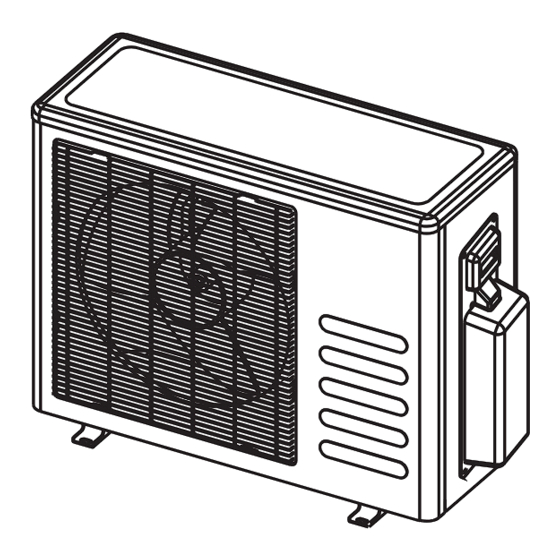
Page 44: Outdoor Unit Installation
Outdoor Unit Installation The area must be free of combustible gases √ Outdoor Unit Installation Instructions and chemicals. √ The pipe length between the outdoor and Step 1: Select installation location. indoor unit may not exceed the maximum The outdoor unit should be installed in the allowable pipe length. - Page 45 OUTDOOR UNIT Unit: mm Model XMX2 18HE XMX3 21HE KMX4 28HE 1034 KMX4 36HE 1034 XMX5 42HE 1034 Rows of series installation The relations between H, A as follows. ≤ 25 cm / 9,8" o più L 1/2H ≤ ≤ 30 cm / 11,8"...
-
Page 46: Drain Joint Installation
NOTE: The minimum distance between the Notes On Drilling Hole In Wall outdoor unit and walls described in the You must drill a hole in the wall for the installation guide does not apply to airtight refrigerant piping, and the signal cable that will rooms. -
Page 47: Refrigerant Piping Connection
Refrigerant Piping Connection Step1: Cut pipes Safety Precautions When preparing refrigerant pipes, take extra care to cut and flare them properly. This will WARNING ensure efficient operation and minimize the • All field piping must be completed by a For R32/R290 need for future maintenance. - Page 48 Pipe Table 7.1: PIPING EXTENSION BEYOND FLARE FORM Reamer Pipe Tightening Flare dimension (A) Flare shape torque (Unit: mm/Inch) gauge Point down Min. Max . 18-20 N.m 90 ° ± 4 8.4/0.33 8.7/0.34 Ø 6.4 (183-204 kgf.cm) 25-26 N.m 13.2/0.52 13.5/0.53 Ø...
- Page 49 7. Thread this pipeline through the wall and NOTE: Use both a spanner and a torque wrench connect it to the outdoor unit. when connecting or disconnecting pipes to/from 8. Insulate all the piping, including the valves the unit. of the outdoor unit. 9.
- Page 50 Wiring Follow these instructions to prevent distortion Safety Precautions when the compressor starts: WARNING • The unit must be connected to the main outlet. Normally, the power supply must • Be sure to disconnect the power supply have a low output impedance of 32 ohms. before working on the unit.
- Page 52 Wiring Figure CAUTION Connect the connective cables to the terminals, as identified, with their matching numbers on the terminal block of the indoor and outdoor units. For example, in the models shown in the following diagram, Terminal L1(A) of the outdoor unit must connect with terminal L1 on the indoor unit.
-
Page 53: L N
L(A) N(A) S(A) L(B) N(B) S(B) S(2) S(A) N(A) L(A) S(2) S(A) N(A) L(A) S(1) S(B) N(B) L(B) L S(1) S(B) N(B) L(B) L POWER POWER SUPPLY SUPPLY TO B TO B TO A TO A Model H Model I Model J NOTE: Please refer to the following figures if end-users wish to perform their own wiring. - Page 54 One-four models: Model A Model B Model C Model D L(A) N(A) S(A) L(B) N(B) S(B) L(C) N(C) S(C) L(D) N(D) S(D) Model E Model F One-five models: Model A Model B Page 22...
- Page 55 Model C Model D 1(C) 2(C) 3(C) 1(D) 2(D) 3(D) 1(E) 2(E) 3(E) 1(A) 2(A) 3(A) 1(B) 2(B) 3(B) L(A) N(A) S(A) L(B) N(B) S(B) L(C) N(C) S(C) L(D) N(D) S(D) L(E) N(E) S(E) TO C TO D TO E TO A TO B TO C...
-
Page 56: Air Evacuation
Air Evacuation NOTE: If there is no change in system pressure, Safety Precautions unscrew the cap from the packed valve (high pressure valve). If there is a change in system CAUTION pressure, there may be a gas leak. • Use a vacuum pump with a gauge reading 8. -
Page 57: Note On Adding Refrigerant
Note On Adding Refrigerant CAUTION • Refrigerant charging must be performed after wiring, vacuuming, and the leak testing. • DO NOT exceed the maximum allowable quantity of refrigerant or overcharge the system. Doing so can damage the unit or impact it’s functioning. •... -
Page 58: Safety And Leakage Check
Safety And Leakage Check Electrical safety check Gas leak check Perform the electrical safety check after 1. Soap water method: completing installation. Cover the following Apply a soap-water solution or a liquid areas: neutral detergent on the indoor unit 1. Insulated resistance connection or outdoor unit connections with The insulated resistance must be more a soft brush to check for leakage of the... -
Page 59: Test Run
Test Run f. Check to see that the drainage system is Before Test Run unimpeded and draining smoothly. A test run must be performed after the entire g. Ensure there is no vibration or abnormal system has been completely installed. Confirm noise during operation. - Page 60 Function of Automatic Wiring/Piping Correction Automatic Wiring/Piping Correction Function More recent models now feature automatic correction of wiring/piping errors. Press the "check switch" on the outdoor unit PCB board for 5 seconds until the LED displays "CE”, indicatomg that this function is working, Approximately 5-10 minutes after the switch is pressed, the "CE" disappears, meaning that the wiring/piping error is corrected and all wiring/piping is properly connected.
- Page 61 European Disposal Guidelines The manufacturer is registered on the EEE National Register, in compliance with implementation of Directive 2012/19/EU and relevant national regulations on waste electrical and electronic equipment. This Directive requires electrical and electronic equipment to be disposed of properly. Equipment bearing the crossed-out wheelie bin mark must be disposed of separately at the end of its life cycle to prevent damage to human health and to the environment.
-
Page 62: Information Servicing
Information Servicing (Required for the units adopt R32/R290 Refrigerant only) 1. Checks to the area Prior to beginning work on systems containing flammable refrigerants, safety checks are necessary to ensure that the risk of ignition is minimised. For repair to the refrigerating system, the following precautions shall be complied with prior to conducting work on the system. - Page 63 the charge size is in accordance with the room size within which the refrigerant containing parts are installed; the ventilation machinery and outlets are operating adequately and are not obstructed; if an indirect refrigerating circuit is being used, the secondary circuits shall be checked for the presence of refrigerant;...
- Page 64 11. Repair to intrinsically safe components Do not apply any permanent inductive or capacitance loads to the circuit without ensuring that this will not exceed the permissible voltage and current permitted for the equipment in use. Intrinscially safe components are the only types that can be worked on while live in the presence of a flammable atmosphere.
- Page 65 When the final OFN charge is used, the system shall be vented down to atmospheric pressure to enable work to take place. This operation is absolutely vital if brazing operations on the pipe-work are to take place. Ensure that the outlet for the vacuum pump is not closed to any ignition sources and there is ventilation available.
- Page 66 18. Labelling Equipment shall be labelled stating that it has been de-commissioned and emptied of refrigerant. The label shall be dated and signed. Ensure that there are labels on the equipment stating the equipment contains flammable refrigerant. 19. Recovery When removing refrigerant from a system, either for service or decommissioning, it is recommended good practice that all refrigerants are removed safely.
Need help?
Do you have a question about the MULTI XMX2 18HE and is the answer not in the manual?
Questions and answers