Table of Contents
Advertisement
Available languages
Available languages
Quick Links
MANUALE UTENTE-INSTALLATORE PER CLIMATIZZATORI SOFFITTO PAVIMENTO
USER'S-INSTALLER'S MANUAL FOR FLOOR CEILING AIR CONDITIONERS
Questo manuale è stato creato per scopo informativo. La ditta declina ogni responsabilità per i risultati di una progettazione o di una installazione basata sulle spiegazioni e le specifiche tecni-
che riportate in questo manuale. E' inoltre vietata la riproduzione anche parziale sotto qualsiasi forma dei testi e delle figure contenute in questo manuale.
This manual has been created for informative purpose. The company declines every responsibility for the results of projecting or installation based on the explanations and the technical speci-
fications given in this manual. Is besides forbidden the reproduction under any form of the texts and of the figures contained in this manual.
PSKM 18HI
PS10 24HI
PS10 36HI
PS10 48HI
PS10 60HI
IT
EN
Advertisement
Chapters
Table of Contents

Related Manuals for Unical PSKM 18HI


Summary of Contents for Unical PSKM 18HI
- Page 1 MANUALE UTENTE-INSTALLATORE PER CLIMATIZZATORI SOFFITTO PAVIMENTO USER’S-INSTALLER'S MANUAL FOR FLOOR CEILING AIR CONDITIONERS PSKM 18HI PS10 24HI PS10 36HI PS10 48HI PS10 60HI Questo manuale è stato creato per scopo informativo. La ditta declina ogni responsabilità per i risultati di una progettazione o di una installazione basata sulle spiegazioni e le specifiche tecni- che riportate in questo manuale.
- Page 2 I prodotti elettrici ed elettronici di eventuale scarto non dovranno essere disposti con i normali rifiuti domestici, ma smaltiti a norma di legge RAEE in base alle direttive Europee 2002/96/CE e suc- cessive modifiche 2003/108/CE, informandosi presso il Comune di residenza o presso il rivenditore nel caso in cui il prodotto venga sostituito con uno analogo. Possible wasted electrical or electronic devices/products should not be located together with normal domestic waste, but disposed according to the current WEEE law in compliance with the European Directive 2002/96/EC and following modifications 2003/108/EC.
-
Page 3: Table Of Contents
Indice Manuale di installazione Accessori ................04 Precauzioni di sicurezza ..........05 Panoramica dell’installazione ......10 Installazione dell’unità interna ......11 a. Componenti dell’unità interna ......11 b. Istruzioni di installazione dell’unità interna ..12 Installazione dell’unità esterna ......16 a. Istruzioni di installazione dell’unità esterna ..16 b. - Page 4 Collegamento delle linee frigorifere ....A. Nota sulla lunghezza e l’altezza dei tubi ....21 B. Istruzioni per il collegamento delle linee frigorifere ..............23 Collega ....25 a. Collegamento elettrico ........b. Collegamento elettrico ........26 c. Requisiti di alimentazione ....27 Evacuazione dell'aria ..........
-
Page 5: Accessori
Accessori Il condizionatore è provvisto dei seguenti accessori. Per installarlo, usare tutti i componenti e gli accessori d’installazione specificati. Un’installazione non corretta può provocare perdite d'acqua, scosse elettriche e incendi, o causare il malfunzionamento dell'apparecchio. Nome Aspetto Quantità Guaina isolante/ Accessori per le fonoassorbente linee frigorifere (alcuni modelli) -
Page 6: Precauzioni Di Sicurezza
Precauzioni di Sicurezza Leggere attentamente le Precauzioni di Sicurezza, prima di iniziare l’installazione Un’installazione errata per aver trascurato le istruzioni può causare gravi danni o lesioni. La gravità di potenziali danni o lesioni è classi cata con “AVVERTENZA” o “ATTENZIONE”. La mancata osservanza di un’avvertenza può... - Page 7 AVVERTENZA 11. Se il cavo di alimentazione è danneggiato, deve essere sostituito dal Servizio Tecnico Autorizzato, per evitare rischi. 12. L’apparecchio deve essere installato in conformità con le norme elettriche nazionali. 13. Un dispositivo di disconnessione onnipolare con almeno 3mm di distanza in tutti i poli, dotato di una corrente di dispersione che superi 10mA, e un dispositivo di corrente residua (RCD) con un valore nominale residuo non superiore a 30mA, devono essere incorporati nel cablaggio sso, in conformità...
- Page 8 Avvertenze per l’utilizzo del refrigerante R32/R290 Installazione (Spazi) - L’installazione delle tubazioni deve essere mantenuta al minimo. - Le tubazioni devono essere protette da danneggiamento. - Rispettare la conformità alle normative nazionali sul gas. - Le connessioni meccaniche devono essere accessibili alla manutenzione. - Nei casi in cui si richiede una ventilazione meccanica, le aperture di ventilazione devono essere tenute libere da ostacoli.
- Page 9 Carica massima di refrigerante (kg) Tabella.1-1 Altezza di Tipo di LFL(kg/m ) Area del pavimento (m Installazione H0(m) Refrigerante 0.68 0.90 1.08 1.32 1.53 1.87 2.41 0.306 1.14 1.51 1.80 2.20 2.54 3.12 4.02 2.05 2.71 3.24 3.97 4.58 5.61 7.24 2.50 3.31...
- Page 10 Spiegazione dei simboli utilizzati nelle illustrazioni delle Unità Interna ed Esterna (applicabili solo alle Unità che utilizzano il Refrigerante R32/R290): Questo simbolo indica che l’apparecchio utilizza un refrigerante in ammabile. Se il refrigerante fuoriesce ed è esposto a fonti di calore in grado di innescare AVVERTENZA amme, c’è...
-
Page 11: Panoramica Dell'installazione
Panoramica dell’installazione SEQUENZA DI INSTALLAZIONE Installare il tubo di scarico Installare l’unità interna Installare l’unità esterna (Pagina 11) (Pagina 16) (Pagina 19) Evacuare il circuito Eseguire i Collegare i tubi del refrigerante (Pagina 21) frigorifero (Pagina 29) collegamenti elettrici (Pagina 25) Eseguire la prova di funzionamento (Pagina 31) Pagina 10... -
Page 12: Installazione Dell'unità Interna
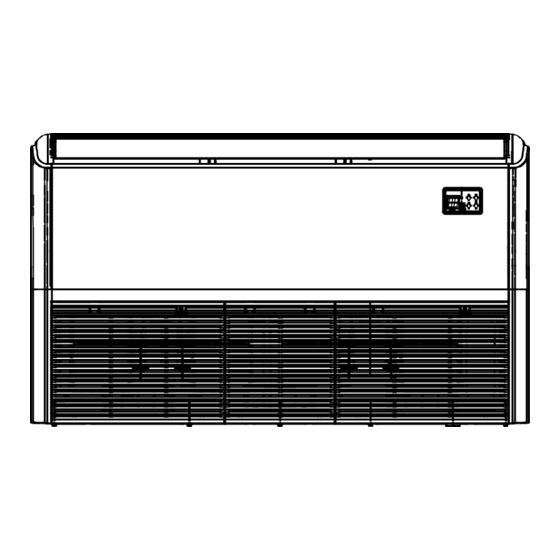
Installazione dell’unità interna Componenti dell’unità interna Elemento di installazione Feritoia di ventilazione Griglia Ingresso aria Pannello del display Uscita aria Fig. 4.1 Precauzioni di sicurezza ATTENZIONE AVVERTENZA • Installare l’unità interna su una struttura • Installare le unità interna ed esterna e i cavi che possa sostenerne il peso. -
Page 13: Istruzioni Di Installazione Dell'unità Interna
Istruzioni di installazione dell’unità interna ATTENZIONE NOTA: l’installazione del pannello deve essere eseguita NON installare l’unità nei seguenti luoghi: dopo avere collegato le tubazioni e i cavi elettrici. Aree di trivellazione o fracking per estrazione Fase 1: Scegliere la posizione di installazione petrolifera L’unità... - Page 14 Collegamento delle linee frigorifere (D. Lato gas) Punto di scarico Collegamento delle linee frigorifere (E. Lato liquido) Gancio Fig. 4.3 Tabella 4.1: Misure di installazione delle parti interne MODELLO Lunghezza A Lunghezza B Lunghezza C Lunghezza D Lunghezza E (Btu/h) (mm/pollici) (mm/pollici) (mm/pollici)
- Page 15 Fase 2: Appendere l’unità interna ATTENZIONE Il corpo dell’unità deve essere perfettamente Legno allineato al foro. Prima di procedere, controllare Posizionare il pannello di montaggio in legno in che l’unità e il foro abbiano la stessa misura. senso trasversale rispetto alla trave del tetto, quindi installare i bulloni di sospensione (Fig.
- Page 16 Installazione a soffitto 8. Rimuovere il pannello laterale e la griglia. (Fig. 4.10). Bullone di Braccio di sospensione sospensione Fig. 4.12 D. Collegamento delle linee frigorifere Pannello (D. Lato gas) laterale Griglia E. Collegamento delle linee frigorifere Fig. 4.10 (E. Lato liquido) 9.
-
Page 17: Installazione Dell'unità Esterna
Installazione dell’unità esterna L’area non deve essere esposta a sostanze Istruzioni di installazione dell’unità esterna chimiche o gas combustibili. La tubazione tra l’unità esterna e quella Fase 1: Scegliere la posizione di installazione. interna non deve superare la lunghezza massima L’unità esterna deve essere installata in un luogo che consentita. -
Page 18: Tipi E Speci Che Delle Unità Esterne
Unità esterna tipo split (Fig 5.4, 5.5, 5.6, 5.10 e Tabella 5.1) Fig. 5.4 Fig. 5.5 Fig. 5.6 Tabella 5.1: Specifiche di lunghezza - Tipo split Unità esterna (mm/pollici) Dimensioni di Dimensioni unità esterna montaggio L x A x P Distanza A Distanza B 800x554x333 (31,5x21,8x13,1) -
Page 19: Note Sulla Foratura Delle Pareti
NOTA: la distanza minima tra l’unità esterna e le Installazione del raccordo di scarico pareti riportata nella guida di installazione non Prima di fissare l’unità esterna in posizione, si applica ai locali a tenuta ermetica. L’unità non è necessario installare il raccordo di scarico deve presentare ostruzioni in almeno due delle tre alla base dell’unità. -
Page 20: Installazione Del Tubo Di Scarico
Installazione del tubo di scarico Il tubo di scarico ha la funzione di scaricare l'acqua dall’unità. Un’installazione non corretta può causare 1-1,5 m (39-59”) danni all’unità e altri danni materiali. ATTENZIONE Pendenza di 1/100 • Isolare tutte le tubazioni per impedire la formazione di condensa, che potrebbe causare Fig. - Page 21 3. Realizzare il foro nella parete usando una punta da 65 mm (2,5”). Il foro dovrà avere una leggera inclinazione, in modo che l’estremità esterna sia più in basso di quella interna di circa 12 mm (0,5”). Questo faciliterà lo scarico dell'acqua (Fig. 6.5). Inserire nel muro il manicotto protettivo, che proteggerà...
-
Page 22: Collegamento Delle Linee Frigorifere
Collegamento delle linee frigorifere Precauzioni di sicurezza Note sulla lunghezza e l’altezza dei tubi La lunghezza del tubo del refrigerante, il numero di AVVERTENZA curve e il dislivello tra l’unità interna e quella esterna devono soddisfare i requisiti indicati nella Tabella 7.1: •... - Page 23 ATTENZIONE ATTENZIONE • Sifoni Se l’Unità Esterna è installata più in alto dell’Unità Interna: Se l’Unità Interna è installata più in alto rispetto all’Unità Esterna -Si raccomanda di non aumentare le dimensioni della tubazione verticale. Il corretto ritorno -Se l’olio ri uisce nel compressore dell’Unità dell’olio al compressore deve essere garantito Esterna, ciò...
-
Page 24: Istruzioni Per Il Collegamento Delle Linee Frigorifere
Fase 2: Eliminare le sbavature. Tabella 7.2 Le sbavature possono rendere meno efficace Lunghezza ammissibile la tenuta ermetica del collegamento delle linee Lunghezza totale tubi 18.000+18.000 30/98’ L+Max frigorifere. Per questa ragione, devono essere (L1, L2) 24.000+24.000 50/164’ eliminate completamente. 30.000+30.000 Lunghez- 1. - Page 25 6. Applicare la vite di svasatura sulla dima. 7. Ruotare la vite in senso orario fino a ottenere la svasatura desiderata. Svasare il tubo secondo le dimensioni indicate nella Tabella 7-3. Tabella 7.3: SPORGENZA DEL TUBO OLTRE LA DIMA Dia- Coppia di Dimensione Forma svasatura Fig.
-
Page 26: Collega
Collegamenti elettrici Per evitare distorsioni dovute all'avvio del compressore Precauzioni di sicurezza (i valori di alimentazione elettrica dell’unità sono riportati sull’etichetta dati dei prodotto): AVVERTENZA • L’unità deve essere collegata alla presa • Prima di eseguire le operazioni scollegare principale. Normalmente, l’alimentazione l’unità... - Page 27 Tabella 8.2: Altri paesi Collegamento elettrico dell'unità interna Corrente nominale 1. Preparare il cavo per il collegamento apparecchio (A) a. Usando uno spelafili, spelare la guaina in 0,75 gomma alle due estremità del cavo di segnale ed esporre circa 15 cm (5,9”) dei conduttori. 6 - 10 b.
-
Page 28: Requisiti Di Alimentazione
Requisiti di alimentazione NOTA: il fusibile o l’interruttore generale del riscaldatore elettrico ausiliario devono avere una portata superiore a 10 A. Requisiti di alimentazione unità interna 19.000~ 25.000~ 37.000~ 49.000~ MODELLO (Btu/h) 18.000 24.000 36.000 48.000 60.000 FASE Monofase Monofase Monofase Monofase Monofase... - Page 29 37.000~ 37.000~ MODELLO (Btu/h) 36.000 36.000 60.000 60.000 FASE Monofase Monofase Monofase Monofase ALIMENTA- ZIONE (unità FREQUENZA 208-240V 208-240V 208-240V 208-240V interna) E TENSIONE INTERRUTTORE 15/10 15/10 15/10 15/10 GENERALE/FUSIBILE (A) FASE Trifase Trifase Trifase Trifase ALIMENTA- ZIONE (unità FREQUENZA 380-420V 380-420V 208-240V 208-240V...
-
Page 30: Evacuazione Dell'aria
Evacuazione dell'aria 4. Attivare la pompa da vuoto per evacuare il sistema. Precauzioni di sicurezza 5. Tenere in funzione la pompa da vuoto per almeno 15 minuti, o finché l’indicatore del manometro di bassa pressione segna -76 cmHG (-1x10⁵ Pa). ATTENZIONE 6. -
Page 31: Nota Sull'aggiunta Di Refrigerante
Nota sull’aggiunta di refrigerante ATTENZIONE • Il refrigerante deve essere caricato dopo avere eseguito il collegamento elettrico e l’evacuazione e dopoavere verificato l'assenza di perdite. • NON superare la quantità massima consentita di refrigerante e non sovraccaricare il sistema. Così facendo si potrebbe danneggiare o compromettere il funzionamento dell’unità. •... -
Page 32: Prova Di Funzionamento
Prova di funzionamento e. I tasti manuali dell’unità interna funzionino Prima della prova di funzionamento correttamente. Dopo avere completato l’installazione del sistema Il sistema di scarico non sia ostruito e l'acqua è necessario eseguire una prova di funzionamento. defluisca liberamente. Prima di eseguire la prova, verificare che: g. -
Page 33: Linee Guida Europee Per Lo Smaltimento
Linee Guida europee per lo Smaltimento Nei paesi dell’Unione Europea può essere obbligatorio per gli utilizzatori provvedere al corretto smaltimento dell’Unità. Questo apparecchio contiene refrigerante e altri materiali potenzialmente pericolosi. Per lo smaltimento di questo apparecchio, le norme di legge prevedono procedure di raccolta e trattamento speciali. -
Page 34: Informazioni Sull'assistenza
Informazioni sull’Assistenza (Per le Unità che adottano il refrigerante R32/R290) 1. Controlli all’area Prima di iniziare a lavorare sui sistemi contenenti refrigeranti infiammabili, è necessario effettuare i controlli di sicurezza per assicurarsi al minimo il rischio di combustione. Prima di procedere con le operazioni di riparazione del sistema refrigerante, occorre rispettare le seguenti avvertenze. - Page 35 la quantità della carica deve essere conforme alle dimensioni della stanza in cui sono installate le parti contenenti refrigerante; le prese di ventilazione devono funzionare regolarmente e non devono essere ostruite; in caso di utilizzo di un circuito frigorifero indiretto, i circuiti secondari devono essere controllati per verificare la presenza di refrigerante;...
- Page 36 sicurezza intrinseca sono l’unico tipo di componenti su cui si può lavorare in presenza di un’atmosfera infiammabile. L’apparecchio di prova deve trovarsi su un valore corretto. Sostituire i componenti solo con i ricambi specificati dal Produttore. A seguito di una perdita, altre parti possono comportare la combustione del refrigerante nell’atmosfera.
- Page 37 Quando viene utilizzata la carica OFN finale, deve essere effettuato lo sfiato del sistema fino alla pressione atmosferica, per consentire l’intervento. Questo passaggio è assolutamente fondamentale se devono essere effettuate le operazioni di brasatura sulle tubazioni. Assicurarsi che la presa della pompa da vuoto non sia vicina a eventuali fonti di combustione e che vi sia un’adeguata ventilazione.
- Page 38 18. Etichettatura Le apparecchiature devono essere etichettate indicando lo smantellamento e lo svuotamento del refrigerante. Sull’etichetta devono essere apposte data e firma. Controllare che sulle apparecchiature siano presenti etichette che indichino la presenza di refrigerante infiammabile. 19. Recupero • In fase di rimozione del refrigerante dal sistema, si raccomanda di adottare la buona prassi per rimuovere in modo sicuro tutti i refrigeranti, sia in caso di assistenza che di smantellamento.
- Page 39 Table of Contents Installation Manual Accessories ............ Safety Precautions ........Installation Overview ....... Indoor Unit Installation Indoor Unit Installation ............a. Indoor Unit Parts ........b. Indoor Unit Installation Instructions ..12 Outdoor Unit Installation ......a. Outdoor Unit Installation Instructions ..
- Page 40 Refrigerant Piping Connection ...... A. Notes on Pipe Length and Elevation ....B. Refrigerant Piping Connection Instructions ... 23 Wiring ..........a. Outdoor Unit Wiring ....b. Indoor Unit Wiring ...... c. Power Specifications ....Air Evacuation ..........a. Evacuation Instructions .......
- Page 41 Accessories The air conditioning system comes with the following accessories. Use all of the installation parts and accessories to install the air conditioner. Improper installation may result in water leakage, electrical shock and re, or equipment failure. Name Shape Quantity Soundproof/insulation Refrigeration Fittings...
- Page 42 Safety Precautions Read Safety Precautions Before Installation Incorrect installation due to ignoring instructions can cause serious damage or injury. The seriousness of potential damage or injuries is classified as either a WARNING or CAUTION. Failure to observe a warning may result in death. The appliance must be installed in accordance with national regulations.
- Page 43 WARNING 11. If the supply cord is damaged, it must be replaced by the manufacturer,its service agent 12. The appliance shall be installed in accordance with national wiring regulations. 13. An all-pole disconnection device which has at least 3mm clearances in all poles, and have a leakage current that may exceed 10mA,the residual current device (RCD) having a rated residual operating current not exceeding 30mA,and disconnection must be 14.
- Page 44 Cautions for using R32/R290 refrigerant Installation (Space) - That the installation of pipe-work shall be kept to a minimum. - That pipe-work shall be protected from physical damage. - That compliance with national gas regulations shall be observed. - That mechanical connections shall be accessible for maintenance purposes. - In cases that require mechanical ventilation, ventilation openings shall be kept clear of obstruction.
- Page 45 Carica massima di refrigerante (kg) Tabella.1-1 Altezza di Tipo di LFL(kg/m ) Area del pavimento (m Installazione H0(m) Refrigerante 0.68 0.90 1.08 1.32 1.53 1.87 2.41 0.306 1.14 1.51 1.80 2.20 2.54 3.12 4.02 2.05 2.71 3.24 3.97 4.58 5.61 7.24 2.50 3.31...
- Page 46 Explanation of symbols displayed on the indoor unit or outdoor unia (applicable to the unit adopts R32/R290 Refrigerant only): WARNING refrigerant is leaked and exposed to an external ignition source, there is a CAUTION This symbol shows that the operation manual should be read carefully. CAUTION This symbol shows that a service personnel should be handling this equipment with reference to the installation manual.
- Page 47 Installation Overview INSTALLATION ORDER Install the indoor unit Install the outdoor unit Install the drainpipe (Page 11) (Page 16) (Page 19) Evacuate the Connect the wires Connect the refrigeration system (Page 25) refrigerant pipes (Page 29) (Page 21) Perform a test run (Page 31) Page 10 ...
-
Page 48: Indoor Unit Installation Indoor Unit Installation
Indoor Unit Installation Indoor Unit Parts Installation part Louver grille Air outlet Display panel Air inlet Fig. 4.1 Safety Precautions CAUTION WARNING • Securely install the indoor unit on a • Install the indoor and outdoor units, cables, structure that can sustain its weight. If the and wires at least 1m (3.2’) from televisions structure is too weak, the unit may fall and and radios to prevent static or image... -
Page 49: Indoor Unit Installation Instructions
Indoor Unit Installation Instructions CAUTION NOTE: Panel installation should be performed DO NOT install the unit in the following after piping and wiring have been completed. locations: Step 1: Select installation location Areas with oil drilling or fracking Coastal areas with high salt content in the The indoor unit should be installed in a location that meets the following requirements: Areas with caustic gases in the air, such as... - Page 50 Refrigerant pipe connection (D. gas side) Drain point Refrigerant pipe connection (E. Liquid side) Hook Fig. 4.3 Table 4.1: Indoor parts installation size MODEL(Btu/h) Length of A (mm/inch) Length of B (mm/inch) Length of C (mm/inch) Length of D (mm/inch) Length of E (mm/inch) 18K~24K 1068/42 675/26.6...
- Page 51 Step 2: Hang indoor unit CAUTION The unit body should align perfectly with the Wood hole. Ensure that the unit and the hole are the Place the square timber traversely over the roof same size before moving on. beam, then install the hanging screw bolts. (See Fig.4.4) 2.
- Page 52 9. Remove the side board and the grille. Ceiling Installation (See Fig. 4.10). Hanging Hanging arm screw bolt Fig. 4.12 D. Refrigerant pipe connection Side board (D.gas side) Grille E. Refrigerant pipe connection Fig. 4.10 (E. Liquid side) 10. Mount the indoor unit onto the hanging screw bolts with a block.
- Page 53 Outdoor Unit Installation The area must be free of combustible gases √ Outdoor Unit Installation Instructions and chemicals. √ The pipe length between the outdoor and Step 1: Select installation location. indoor unit may not exceed the maximum The outdoor unit should be installed in the allowable pipe length.
- Page 54 Split Type Outdoor Unit (Refer to Fig 5.4, 5.5, 5.6, 5.10 and Table 5.1) Fig. 5.4 Fig. 5.5 Fig. 5.6 Table 5.1: Length Specifications of Split Type Outdoor Unit (unit: mm/inch) Outdoor Unit Dimensions Mounting Dimensions W x H x D Distance A Distance B 760x590x285 (29.9x23.2x11.2)
- Page 55 NOTE: The minimum distance between the 2. Insert the drain joint into the hole in the base outdoor unit and walls described in the pan of the unit. installation guide does not apply to airtight 3. Rotate the drain joint 90° until it clicks in place rooms.
-
Page 56: Drainpipe Installation
Drainpipe Installation The drainpipe is used to drain water from the unit. Improper installation may cause unit and 1-1.5m (39-59”) property damage. CAUTION Downward slope 1/100 Insulate all piping to prevent condensation • Fig. 6.2 and water damage. If the drainpipe is bent or installed •... - Page 57 Using a 65-mm (2.5”) core drill, drill a hole in the wall. Make sure that the hole is drilled at a slight downward angle, so that the outdoor end of the hole is lower than the indoor end by about 12mm (0.5”). This will ensure proper water drainage (See Fig.
-
Page 58: Refrigerant Piping Connection
Refrigerant Piping Connection Safety Precautions Notes On Pipe Length and Elevation Ensure that the length of the refrigerant pipe, the WARNING number of bends, and the drop height between the indoor and outdoor units meets the • All eld piping must be completed by a requirements shown in Table 7.1: licensed technician and must comply with the local and national regulations. - Page 59 CAUTION CAUTION • Oil traps If the outdoor unit is installed higher than the indoor unit: If the indoor unit is installed higher than the outdoor unit: -It is recommended that vertical suction risers not be upsized. Proper oil return to the -If oil flows back into the outdoor unit’s compressor should be maintained with suction compressor, this might cause liquid...
-
Page 60: Refrigerant Piping Connection Instructions
Table 7.2 Step 2: Remove burrs. Burrs can a ect the air-tight seal of refrigerant Permitted length piping connection. They must be completely Total piping length 18K+18K 30m/98’ L+Max (L1, L2) removed. 24K+24K 50m/164’ 1. Hold the pipe at a downward angle to 30K+30K prevent burrs from falling into the pipe. - Page 61 6. Place flaring tool onto the form. 7. Turn the handle of the flaring tool clockwise until the pipe is fully flared. Flare the pipe in accordance with the dimensions shown in table 7.3. Table 7.3: PIPING EXTENSION BEYOND FLARE FORM Fig.
- Page 62 Wiring Follow these instructions to prevent distortion Safety Precautions when the compressor starts: • The unit must be connected to the main WARNING outlet. Normally, the power supply must • Be sure to disconnect the power supply have a low output impedance of 32 ohms. before working on the unit.
- Page 63 Table 8.2: Other Regions Indoor Unit Wiring Rated Current of Nominal Cross-Sectional 1. Prepare the cable for connection Appliance (A) Area (mm²) a. Using wire strippers, strip the rubber jacket 0.75 ≤ from both ends of a signal cable to reveal 6 - 10 about 15cm (5.9”) of the wires inside.
- Page 64 CAUTION While connecting the wires, please strictly follow the wiring diagram. • The refrigerant circuit can become very hot. Keep the interconnection cable away from the • copper tube. 5. Clamp down the cable with the designated cable clamp to secure it in place. The cable should not be loose and should not pull on the u-lugs.
- Page 65 Independent Power Supply Specifications ≤18K MODEL(Btu/h) 19K~24K 25K~36K 37K~48K 49K~60K PHASE 1 Phase 1 Phase 1 Phase 1 Phase 1 Phase POWER FREQUENCY (indoor) 208-240V 208-240V 208-240V 208-240V 208-240V AND VOLT CIRCUIT BREAKER/ 15/10 15/10 15/10 15/10 15/10 FUSE(A) PHASE 1 Phase 1 Phase 1 Phase...
-
Page 66: Air Evacuation
Air Evacuation 4. Turn on the vacuum pump to evacuate the Safety Precautions system. 5. Run the vacuum for at least 15 minutes, or until the Compound Meter reads -76cmHG CAUTION (-1x10⁵Pa). 6. Close the manifold gauge’s Low Pressure valve •... -
Page 67: Note On Adding Refrigerant
Note On Adding Refrigerant CAUTION • Refrigerant charging must be performed after wiring, vacuuming, and the leak testing. DO NOT exceed the maximum allowable quantity of refrigerant or overcharge the system. • Doing so can damage the unit or impact it’s functioning. •... -
Page 68: Test Run
Test Run f. Check to see that the drainage system is Before Test Run unimpeded and draining smoothly. A test run must be performed after the entire g. Ensure there is no vibration or abnormal system has been completely installed. Confirm noise during operation. -
Page 69: European Disposal Guidelines
European Disposal Guidelines Users in European Countries may be required to properly dispose of this unit. This appliance contains refrigerant and other potentially hazardous materials. When disposing of this appliance, the law requires special collection and treatment. DO NOT dispose of this product as household waste or unsorted municipal waste. -
Page 70: Information Servicing
Information Servicing (Required for the Units adopt R32/R290 Refrigerant only) 1. Checks to the area Prior to beginning work on systems containing ammable refrigerants, safety checks are necessary to ensure that the risk of ignition is minimised. For repair to the refrigerating system, the following precautions shall be complied with prior to conducting work on the system. - Page 71 the charge size is in accordance with the room size within which the refrigerant containing parts are installed; the ventilation machinery and outlets are operating adequately and are not obstructed; if an indirect refrigerating circuit is being used, the secondary circuits shall be checked for the presence of refrigerant;...
- Page 72 11. Repair to intrinsically safe components Do not apply any permanent inductive or capacitance loads to the circuit without ensuring that this will not exceed the permissible voltage and current permitted for the equipment in use. Intrinscially safe components are the only types that can be worked on while live in the presence of a ammable atmosphere.
- Page 73 When the final OFN charge is used, the system shall be vented down to atmospheric pressure to enable work to take place. This operation is absolutely vital if brazing operations on the pipe-work are to take place. Ensure that the outlet for the vacuum pump is not closed to any ignition sources and there is ventilation available.
- Page 74 18. Labelling Equipment shall be labelled stating that it has been de-commissioned and emptied of refrigerant. The label shall be dated and signed. Ensure that there are labels on the equipment stating the equipment contains flammable refrigerant. 19. Recovery When removing refrigerant from a system, either for service or decommissioning, it is recommended good practice that all refrigerants are removed safely.
- Page 76 - export@unical-ag.com - www.unical.eu Unical declina ogni responsabilità per le possibili inesattezze se dovute ad errori di trascrizione o di stampa. Si riserva altresì il diritto di apportare ai propri prodotti quelle modifi che che riterrà necessarie o utili, senza pregiudicarne le caratteristiche essenziali.
Need help?
Do you have a question about the PSKM 18HI and is the answer not in the manual?
Questions and answers