
Related Manuals for Unical MULTI KMPS 12 HI


Summary of Contents for Unical MULTI KMPS 12 HI
- Page 1 MULTI KMPS 12 HI ISTRUZIONI PER L’INSTALLATORE E IL MANUTENTORE INSTALLATION AND SERVICING MANUAL...
-
Page 3: Table Of Contents
Indice Manuale di installazione NOTA IMPORTANTE: Leggere attentamente questo manuale prima di installare o mettere in funzione il nuovo condizionatore d'aria. Conservare questo manuale per eventuali consultazioni future. 1 Accessori ................04 2 Precauzioni di sicurezza ........05 3 Panoramica dell’installazione ......06 4 Installazione dell’unità interna ......07 e. - Page 4 7 Collegamento delle linee frigorifere ....17 H. Note sulla lunghezza e l’elevazione dei tubi .............17 I. Istruzioni per il collegamento delle linee frigorifere ................18 8 Collegamento elettrico ....... 20 i. Collegamento elettrico dell’unità esterna ......... 20 j. Collegamento elettrico dell’unità interna .........
-
Page 5: Accessori
Accessori Il condizionatore è provvisto dei seguenti accessori. Per installarlo, usare tutti i componenti e gli accessori d’installazione specificati. Un’installazione non corretta può provocare perdite d'acqua, scosse elettriche e incendi, o causare il malfunzionamento dell'apparecchio. QUANTITÀ NOME ASPETTO Accessori per le linee Guaina isolante/fonoassorbente (alcuni modelli) frigorifere Componenti di... -
Page 6: Precauzioni Di Sicurezza
Precauzioni di sicurezza Leggere le precauzioni di sicurezza prima di eseguire l’installazione Un’installazione non corretta dovuta al mancato rispetto delle istruzioni può causare danni o lesioni gravi. Per classificare la gravità dei potenziali danni o lesioni vengono usate le diciture AVVERTENZA o ATTENZIONE. La mancata osservanza delle precauzioni identificate con questa dicitura può... -
Page 7: Panoramica Dell'installazione
Panoramica dell’installazione SEQUENZA DI INSTALLAZIONE Installare l’unità interna Installare l’unità esterna Installare il tubo di scarico (Pagina 7) (Pagina 13) (Pagina 15) Evacuare il gruppo idronico Eseguire i collegamenti Collegare i tubi del (Pagina 23) elettrici refrigerante (Pagina 20) (Pagina 17) Eseguire la prova di funzionamento (Pagina 25) -
Page 8: Installazione Dell'unità Interna
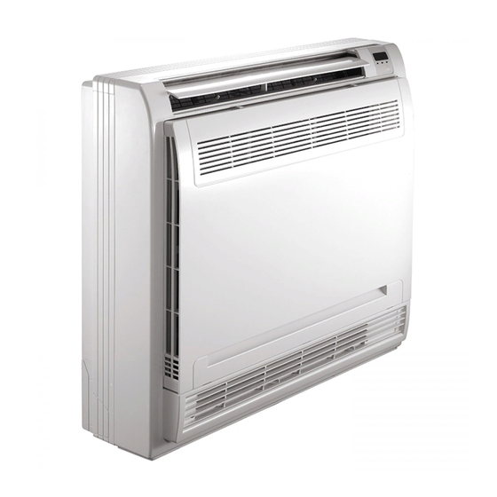
Installazione dell’unità interna Componenti dell’unità interna Feritoia di ventilazione Pannello del display (uscita aria) Ingresso aria (con filtro) Feritoia di ventilazione Tubo del refrigerante (uscita aria) Tubo di scarico Fig. 4.1 Precauzioni di sicurezza AVVERTENZA ATTENZIONE • Installare l’unità interna su una struttura •... -
Page 9: Istruzioni Di Installazione Dell'unità Interna
Istruzioni di installazione dell’unità interna ATTENZIONE NOTA: l’installazione del pannello deve essere eseguita NON installare l’unità nei seguenti luoghi: dopo avere collegato le tubazioni e i cavi elettrici. Aree di trivellazione o fracking per estrazione petrolifera Fase 1: Scegliere la posizione di installazione Aree costiere con aria fortemente salmastra L’unità... - Page 10 700 mm 210 mm 195 mm Gancio Fig. 4.3...
- Page 11 Fase 2: Installazione del corpo principale • Fissare i ganci alla parete usando viti autofilettanti. Gancio Vite autofilettante Rondella < 6 mm Fig. 4.4 • Appendere l’unità interna ai ganci. (La base del corpo può essere a contatto con il pavimento o sospesa, ma il corpo deve essere installato verticalmente.) Fig.
- Page 12 Fase 3: Aprire l’unità interna per eseguire 3. Rimuovere la piastra anteriore. il collegamento dei tubi Rimuovere le quattro viti. (Fig.4.7) Aprire la piastra anteriore dal basso a un angolo 1. Aprire il pannello anteriore. di 30 gradi. Sollevare la piastra anteriore. (Fig.4.8) Far scorrere i due fermi posti a destra e a sinistra verso il centro fino allo scatto.
-
Page 13: Installazione Dell'unità Esterna
Installazione dell’unità esterna (sistemi Light Commercial) L’area non deve essere esposta a sostanze Istruzioni di installazione dell’unità esterna chimiche o gas combustibili. Fase 1: Scegliere la posizione di installazione La tubazione tra l’unità esterna e quella interna non L’unità esterna deve essere installata in un luogo deve superare la lunghezza massima consentita. -
Page 14: Tipi E Specifiche Delle Unità Esterne
Unità esterna tipo split NOTA: la distanza minima tra l’unità esterna e le (Fig 5.4, 5.5, 5.6 e Tabella 5.1) pareti riportata nella guida di installazione non si applica ai locali a tenuta ermetica. L’unità non deve presentare ostruzioni in almeno due delle tre direzioni (M, N, P) (Fig. -
Page 15: Note Sulla Foratura Delle Pareti
Installazione del raccordo di scarico Prima di fissare l’unità esterna in posizione, è necessario installare il raccordo di scarico alla base dell’unità. (Fig. 5.8) 1. Applicare la guarnizione di gomma all'estremità del raccordo di scarico da collegare all’unità esterna. 2. Inserire il raccordo di scarico nel foro situato nel pannello di base dell’unità. -
Page 16: Installazione Del Tubo Di Scarico
Installazione del tubo di scarico Il tubo di scarico ha la funzione di scaricare l'acqua dall’unità. Un’installazione non corretta può causare danni all’unità e altri danni materiali. ATTENZIONE • Isolare tutte le tubazioni per impedire la formazione di condensa, che potrebbe causare danni dovuti all'acqua. - Page 17 3. Realizzare il foro nella parete usando una punta da 65 mm (2,5”). Il foro dovrà avere una leggera inclinazione, in modo che l’estremità esterna sia più in basso di quella interna di circa 12 mm (0,5”). Questo faciliterà lo scarico dell'acqua (Fig. 6.4).
-
Page 18: Collegamento Delle Linee Frigorifere
Collegamento delle linee frigorifere Precauzioni di sicurezza Note sulla lunghezza e l’elevazione dei tubi La lunghezza del tubo del refrigerante, il numero di curve e il dislivello tra l’unità interna e quella esterna AVVERTENZA devono soddisfare i requisiti indicati nella Tabella 7.1: •... -
Page 19: Istruzioni Per Il Collegamento Delle Linee Frigorifere
Fase 2: Eliminare le sbavature. Istruzioni per il collegamento delle linee frigorifere Le sbavature possono rendere meno efficace la tenuta ermetica del collegamento delle linee frigorifere. Per questa ragione, devono essere ATTENZIONE eliminate completamente. • Il tubo di derivazione deve essere installato 1. - Page 20 6. Applicare la vite di svasatura sulla dima. 7. Ruotare la vite in senso orario fino a ottenere la svasatura desiderata. Svasare il tubo secondo le dimensioni indicate nella Tabella 7.2. Tabella 7.2: SPORGENZA DEL TUBO OLTRE LA DIMA Fig. 7.7 Diametro Coppia Dimensione svasatura...
-
Page 21: Collegamento Elettrico
Collegamenti elettrici Per evitare distorsioni dovute all'avvio del compressore Precauzioni di sicurezza (i valori di alimentazione elettrica dell’unità sono riportati sulla targhetta dati): AVVERTENZA • L’unità deve essere collegata alla presa • Prima di eseguire le operazioni scollegare principale. Normalmente, l’alimentazione deve l’unità... -
Page 22: Collegamento Elettrico Dell'unità Interna
Tabella 8.2: Collegamento elettrico delle unità interne Altri paesi 1. Preparare il cavo per il collegamento b. Usando uno spelafili, spelare la guaina in Massima assorbita Sezione nominale (mm²) gomma alle due estremità del cavo di segnale ed esporre circa 15 cm (5,9”) dei conduttori. ≤... -
Page 23: Requisiti Di Alimentazione
Requisiti di alimentazione MODELLO (Btu/h) <16.000 16.000~18.000 FASE Monofase Monofase ALIMENTAZIONE FREQUENZA E TENSIONE 220-240V~, 50Hz/60Hz 220-240V~, 50Hz/60Hz INTERRUTTORE GENERALE/FUSIBILE (A) 20/16 20/16 CAVO DI ALIMENTAZIONE UNITÀ INTERNA (mm²) —— 3x1,0 CAVO DI ALIMENTAZIONE 3x1,5 3x2,5 UNITÀ ESTERNA CAVO DI SEGNALE ELETTRICO COLLEGAMENTO 4x1,0... -
Page 24: Evacuazione Dell'aria
Evacuazione dell'aria 4. Attivare la pompa da vuoto per evacuare il sistema. Precauzioni di sicurezza 5. Tenere in funzione la pompa da vuoto per almeno 15 minuti, o finché l’indicatore del manometro di bassa pressione segna -76 cmHG (-1x10 Pa). ATTENZIONE 6. - Page 25 Nota sull’aggiunta di refrigerante ATTENZIONE • Il refrigerante deve essere caricato dopo avere eseguito il collegamento elettrico e l’evacuazione e dopo avere verificato l'assenza di perdite. • NON superare la quantità massima consentita di refrigerante e non sovraccaricare il sistema. Così facendo si potrebbe danneggiare o compromettere il funzionamento dell’unità.
- Page 26 Prova di funzionamento d. Gli indicatori sul telecomando e il display Prima della prova di funzionamento dell’unità interna funzionino correttamente. Dopo avere completato l’installazione del sistema e. I tasti manuali dell’unità interna è necessario eseguire una prova di funzionamento. funzionino correttamente. Prima di eseguire la prova, verificare che: Il sistema di scarico non sia ostruito e l'acqua a) Le unità...
- Page 27 Linee guida europee per lo smaltimento Il produttore è iscritto al Registro Nazionale AEE, in conformità all’attuazione della direttiva 2012/19/UE e delle relative norme nazionali vigenti sui rifiuti di apparecchiature elettriche ed elettroniche. Tale direttiva raccomanda il corretto smaltimento delle apparecchiature elettriche ed elettroniche. Quelle che riportano il marchio del bidoncino sbarrato devono essere smaltite a fine ciclo di vita in modo differenziato al fine di scongiurare danni per la salute umana e per l’ambiente.
- Page 28 Informazioni sull’assistenza (Necessarie solo per le unità che adotta il refrigerante R32/R290) 1. Controlli all’area Prima di iniziare a lavorare sui sistemi contenenti refrigeranti infiammabili, è necessario effettuare i controlli di sicurezza per assicurarsi di ridurre al minimo il rischio di combustione. Prima di procedere con le operazioni di riparazione del sistema refrigerante, occorre rispettare le seguenti avvertenze.
- Page 29 • la quantità della carica deve essere conforme alle dimensioni della stanza in cui sono installate le parti contenenti refrigerante; • il macchinario e la presa di ventilazione funzionano correttamente e non presentano ostruzioni; • se viene impiegato un circuito refrigerante indiretto, i circuiti secondari dovranno essere controllati per verificare la presenza di refrigerante;...
- Page 30 11. Riparazione dei componenti a sicurezza intrinseca Non applicare carichi induttivi o capacitivi permanenti al circuito senza garantire che non superino la tensione ammissibile e la corrente consentita per le apparecchiature in uso. I componenti a sicurezza intrinseca sono l’unico tipo di componenti su cui si può lavorare in presenza di un’atmosfera infiammabile. L’apparecchio di prova deve trovarsi su un valore corretto.
- Page 31 Quando viene utilizzata la carica OFN finale, deve essere effettuato lo sfiato del sistema fino alla pressione atmosferica, per consentire l’intervento. Questo passaggio è assolutamente fondamentale se devono essere effettuate le operazioni di brasatura sulle tubazioni. Assicurarsi che la presa della pompa da vuoto non sia vicina a eventuali fonti di accensione e che vi sia un’adeguata ventilazione.
- Page 32 18. Etichettatura Le apparecchiature devono essere etichettate indicando lo smantellamento e lo svuotamento del refrigerante. Sull’etichetta devono essere apposte data e firma. Controllare che sulle apparecchiature siano presenti etichette che indichino la presenza di refrigerante infiammabile. 19. Recupero • In fase di rimozione del refrigerante dal sistema, si raccomanda di adottare la buona prassi per rimuovere in modo sicuro tutti i refrigeranti, sia in caso di assistenza che di smantellamento.
- Page 33 Informazioni tecniche Caratteristiche tecniche (MultiSplit) Unità esterna MU1-Y 105M 125M Linee frigorifere Dual 1~2 Dual 1~2 Triple 1~3 Triple 1~3 Quadri 1~4 Quadri 1~4 Penta 1~5 Unità interne collegabili (Min ~Max) 2x1/4” 2x1/4” 3x1/4” 3x1/4” 4x1/4” 4x1/4” 5x1/4” Linea liquido 2x6,35 2x6,35 3x6,35...
- Page 34 Caratteristiche tecniche (Light Commercial) Unità esterna MC2-Y 105M 105T 140T 160T Linee frigorifere 1/4” 1/4” 3/8” 3/8” 3/8” 3/8” 3/8” Linea liquido 6,35 6,35 9,52 9,52 9,52 9,52 9,52 3/8” 1/2” 5/8” 5/8” 5/8” 5/8” 5/8” Linea gas 9,52 12,7 15,9 15,9 15,9...
- Page 35 Table of Contents Installation Manual IMPORTANT NOTE: Read this manual carefully before installing or operating your new air conditioning unit. Make sure to save this manual for future reference. Accessories ............ Safety Precautions ........Installation Overview ....... Indoor Unit Installation ......
- Page 36 Refrigerant Piping Connection ....... A. Notes on Pipe Length and Elevation ....17 B. Refrigerant Piping Connection Instructions ...18 Wiring ..........a. Outdoor Unit Wiring ....b. Indoor Unit Wiring ..... c. Power Specifications ....Air Evacuation ..........a. Evacuation Instructions ........
- Page 37 Accessories The air conditioning system comes with the following accessories. Use all of the installation parts and accessories to install the air conditioner. Improper installation may result in water leakage, electrical shock and fire, or equipment failure. NAME SHAPE QUANTITY Soundproof / insulation sheath (some models) Refrigeration Fittings Installation Fittings...
- Page 38 Safety Precautions Read Safety Precautions Before Installation Incorrect installation due to ignoring instructions can cause serious damage or injury. The seriousness of potential damage or injuries is classified as either a WARNING or CAUTION. Failure to observe a warning may result in death. The appliance must be installed in accordance with national regulations.
- Page 39 Installation Overview INSTALLATION ORDER Install the indoor unit Install the outdoor unit Install the drainpipe (Page 7) (Page 13) (Page 15) Evacuate the refrigeration system Connect the wires Connect the refrigerant pipes (Page 23) (Page 20) (Page 17) Perform a test run (Page 25)
-
Page 40: Indoor Unit Installation
Indoor Unit Installation Indoor Unit Parts Air flow louver (at air outlet) Display panel Air inlet (with air filter in it) Air flow louver (at air outlet) Refrigerant connecting pipe Drain hose Fig. 4.1 Safety Precautions CAUTION WARNING • Securely install the indoor unit on a •... -
Page 41: Indoor Unit Installation Instructions
Indoor Unit Installation Instructions CAUTION NOTE: Panel installation should be performed DO NOT install the unit in the following after piping and wiring have been completed. locations: Areas with oil drilling or fracking Step 1: Select installation location Coastal areas with high salt content in the The indoor unit should be installed in a location that meets the following requirements: Areas with caustic gases in the air, such as... - Page 42 700mm 210mm 195mm Hook Fig. 4.3...
- Page 43 Step 2: Installing the main body Affix the hook with a tapping screw onto the wall. Hook Tapping screw Washer Fig. 4.4 Hang the indoor unit on the hook. (The bottom of body can touch the floor or remain suspended, but the body must be installed vertically.) Fig.
- Page 44 Step 3: Taking the indoor unit apart to 3. Remove the face plate. connect the pipes Remove the four screws.(See Fig.4.7) 1. Open the front panel Open the bottom of the face plate at a 30-degree angle. Lift the top of the face Slide the two stoppers on the left and right plate.
- Page 45 Outdoor Unit Installation (LIGHT Commercial systems) The area must be free of combustible gases √ Outdoor Unit Installation Instructions and chemicals. The pipe length between the outdoor and √ Step 1: Select installation location. indoor unit may not exceed the maximum The outdoor unit should be installed in the allowable pipe length.
- Page 46 NOTE: The minimum distance between the Split Type Outdoor Unit outdoor unit and walls described in the (Refer to Fig 5.4, 5.5, 5.6 and Table 5.1) installation guide does not apply to airtight rooms. Be sure to keep the unit unobstructed in at least two of the three directions (M, N, P) (See Fig.
- Page 47 Drain Joint Installation Before bolting the outdoor unit in place, you must install the drain joint at the bottom of the unit. (See Fig. 5.8) 1. Fit the rubber seal on the end of the drain joint that will connect to the outdoor unit. 2.
-
Page 48: Drainpipe Installation
Drainpipe Installation The drainpipe is used to drain water away from the unit. Improper installation may cause unit and property damage. CAUTION Insulate all piping to prevent condensation, • which could lead to water damage. If the drainpipe is bent or installed •... - Page 49 3. Using a 65-mm (2.5”) core drill, drill a hole in the wall. Make sure that the hole is drilled at a slight downward angle, so that the outdoor end of the hole is lower than the indoor end by about 12mm (0.5”). This will ensure proper water drainage (See Fig.
-
Page 50: Refrigerant Piping Connection
Refrigerant Piping Connection Safety Precautions Notes On Pipe Length and Elevation Ensure that the length of the refrigerant pipe, the number of bends, and the drop height between WARNING the indoor and outdoor units meets the • All field piping must be completed by a requirements shown in Table 7.1: licensed technician and must comply with the local and national regulations. -
Page 51: Refrigerant Piping Connection Instructions
Step 2: Remove burrs. Refrigerant Piping Connection Instructions Burrs can affect the air-tight seal of refrigerant piping connection. They must be completely CAUTION removed. 1. Hold the pipe at a downward angle to The branching pipe must be installed • prevent burrs from falling into the pipe. - Page 52 6. Place flaring tool onto the form. 7. Turn the handle of the flaring tool clockwise until the pipe is fully flared. Flare the pipe in accordance with the dimensions shown in table 7.2. Table 7.2: PIPING EXTENSION BEYOND FLARE Fig.
- Page 53 Wiring To prevent distortion when the compressor starts Safety Precautions (you can find the unit’s power information on the rating sticker): WARNING • The unit must be connected to the main • Disconnect the power supply before outlet. Normally, the power supply must working on the unit.
- Page 54 Table 8.2: Other World Regions Indoor Unit Wiring 1. Prepare the cable for connection Absorbed Nominal Cross-Sectional a. Using wire strippers, strip the rubber jacket maximum (A) Area (mm²) from both ends of the signal cable to reveal 0.75 about 15cm (5.9”) of the wire. 6 - 10 b.
- Page 55 Power Specifications MODEL(Btu/h) 16K~18K PHASE 1 Phase 1 Phase POWER FREQUENCY AND VOLT 220-240V~,50Hz/60Hz 220-240V~,50Hz/60Hz CIRCUIT BREAKER/FUSE(A) 20/16 20/16 INDOOR UNIT POWER WIRING(mm²) —— 3x1.0 OUTDOOR UNIT 3x1.5 3x2.5 POWER WIRING INDOOR/OUDOOR STRONG ELECTRIC 4x1.0 —— CONNECTING SIGNAL WIRING(mm²) WEAK ELECTRIC 3x0.2 ——...
-
Page 56: Air Evacuation
Air Evacuation 4. Turn on the vacuum pump to evacuate the Safety Precautions system. 5. Run the vacuum for at least 15 minutes, or until the Compound Meter reads -76cmHG CAUTION (-1x10⁵Pa). 6. Close the manifold gauge’s Low Pressure valve •... -
Page 57: Note On Adding Refrigerant
Note On Adding Refrigerant CAUTION • Refrigerant charging must be performed after wiring, vacuuming, and the leak testing. DO NOT exceed the maximum allowable quantity of refrigerant or overcharge the system. • Doing so can damage the unit or impact it’s functioning. •... -
Page 58: Test Run
Test Run f. Check to see that the drainage system is Before Test Run unimpeded and draining smoothly. A test run must be performed after the entire g. Ensure there is no vibration or abnormal system has been completely installed. Confirm noise during operation. -
Page 59: European Disposal Guidelines
European Disposal Guidelines The manufacturer is registered on the EEE National Register, in compliance with implementation of Directive 2012/19/EU and relevant national regulations on waste electrical and electronic equipment. This Directive requires electrical and electronic equipment to be disposed of properly. Equipment bearing the crossed-out wheelie bin mark must be disposed of separately at the end of its life cycle to prevent damage to human health and to the environment. -
Page 60: Information Servicing
Information Servicing (Required for the units adopt R32/R290 Refrigerant only) 1. Checks to the area Prior to beginning work on systems containing flammable refrigerants, safety checks are necessary to ensure that the risk of ignition is minimised. For repair to the refrigerating system, the following precautions shall be complied with prior to conducting work on the system. - Page 61 the charge size is in accordance with the room size within which the refrigerant containing parts are installed; the ventilation machinery and outlets are operating adequately and are not obstructed; if an indirect refrigerating circuit is being used, the secondary circuits shall be checked for the presence of refrigerant;...
- Page 62 11. Repair to intrinsically safe components Do not apply any permanent inductive or capacitance loads to the circuit without ensuring that this will not exceed the permissible voltage and current permitted for the equipment in use. Intrinscially safe components are the only types that can be worked on while live in the presence of a flammable atmosphere.
- Page 63 When the final OFN charge is used, the system shall be vented down to atmospheric pressure to enable work to take place. This operation is absolutely vital if brazing operations on the pipe-work are to take place. Ensure that the outlet for the vacuum pump is not closed to any ignition sources and there is ventilation available.
- Page 64 18. Labelling Equipment shall be labelled stating that it has been de-commissioned and emptied of refrigerant. The label shall be dated and signed. Ensure that there are labels on the equipment stating the equipment contains flammable refrigerant. 19. Recovery When removing refrigerant from a system, either for service or decommissioning, it is recommended good practice that all refrigerants are removed safely.
-
Page 65: Technical Information
Technical information Technical features (MultiSplit) Outdoor unit MU1-Y 105M 125M Refrigerant lines Dual 1 2 Dual 1 2 Triple 1 3 Triple 1 3 Quadri 1 4 Quadri 1 4 Penta 1 5 Indoor units connectable (Min 2x1/4” 2x1/4” 3x1/4” 3x1/4”... - Page 66 Technical features (Light Commercial) Outdoor unit MC2-Y 105M 105T 140T 160T Refrigerant lines 1/4” 1/4” 3/8” 3/8” 3/8” 3/8” 3/8” Liquid line 6,35 6,35 9,52 9,52 9,52 9,52 9,52 3/8” 1/2” 5/8” 5/8” 5/8” 5/8” 5/8” Gas line 9,52 12,7 15,9 15,9 15,9...
- Page 68 Si riserva altresì il diritto di apportare ai propri prodotti quelle modifiche che riterrà necessarie o utili, senza pregiudicarne le caratteristiche essenziali. Unical will not be held responsible for possible inaccuracies if due to transcription or printing errors. It also reserves the...
Need help?
Do you have a question about the MULTI KMPS 12 HI and is the answer not in the manual?
Questions and answers