Table of Contents
Advertisement
Available languages
Available languages
Advertisement
Chapters
Table of Contents

Related Manuals for Unical HP OWER 260RK


Summary of Contents for Unical HP OWER 260RK
- Page 1 260RK - 320RK ISTRUZIONI INTERFACCIA UTENTE CONTROLLER MANUAL...
-
Page 2: Table Of Contents
Indice 1. SCOPO E CONTENUTO DEL MANUALE ................5 1.1CONSERVAZIONE DEL MANUALE ................... 5 1.2CONVENZIONI GRAFICHE UTILIZZATE NEL MANUALE ........... 5 2. USO CONSENTITO ......................5 3. NORMATIVE GENERALI SULLA SICUREZZA ..............5 3.1MEZZI DI PROTEZIONE PERSONALE ................6 3.2SICUREZZA E SALUTE DEI LAVORATORI ................6 3.3SEGNALAZIONI DI SICUREZZA .................. - Page 3 11.RESISTENZA DEL CARTER DEL COMPRESSORE ............. 14 12.PRODUZIONE ACQUA CALDA SANITARIA ..............14 12.1.1 MEMORIZZAZIONE DELLA SONDA IN CALDO ............15 12.1.2 MODO CALDO SU ACCUMULO SANITARIA ............15 13.FUNZIONI DA REMOTO ....................15 13.1 ON/OFF ........................15 13.2 CAMBIO MODO ESTATE/INVERNO ................ 15 13.3 CHIAMATA SANITARIA DA INGRESSO DIGITALE ............
- Page 4 22.14 MANCANZA DI TENSIONE ..................27 22.15 TABELLA ALLARMI BLOCCO UTENZE ..............28 23.VARIABILI MODBUS ....................... 28...
-
Page 5: Scopo E Contenuto Del Manuale
1. SCOPO E CONTENUTO DEL MANUALE Il manuale del controllo per le unità 260RK-320RK ha lo scopo di fornire le informazioni necessarie per consentire un corretto utilizzo di tutte le funzionalità della macchina, in particolare si propone di fornire le informazioni essenziali per la configurazione del controllo delle unità. Le indi- cazioni contenute nel presente manuale sono scritte per l’installatore e per l’utente che utilizza la macchina: quest’ultimo, anche non avendo nozioni specifiche, troverà... -
Page 6: Mezzi Di Protezione Personale
È VIETATO: Rimuovere e/o manomettere qualsiasi dispositivo di sicurezza. Accedere al quadro elettrico ai non autorizzati. Toccare gli impianti se non si è autorizzati. Effettuare qualsiasi operazione di pulizia quando l’interruttore elettrico principale è in ‘ON’. Tirare, staccare, torcere i cavi elettrici dall’apparecchio. Salire con i piedi sull’apparecchio, sedersi e/o appoggiarvi qualsiasi tipo di oggetto. -
Page 7: Display
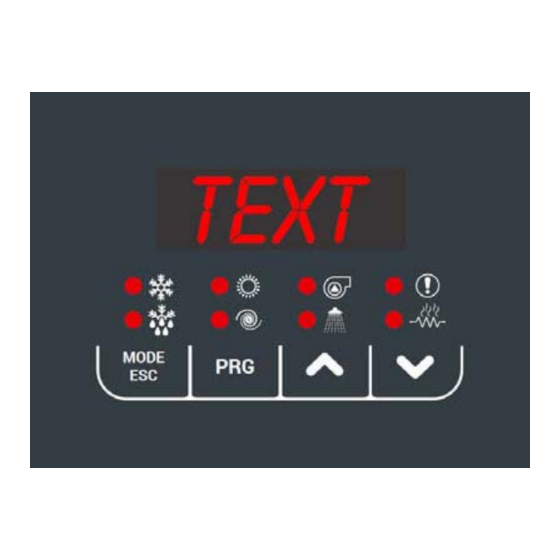
4.1 DISPLAY 4.1.1 TASTI Seleziona il modo di funzionamento, e resetta gli allarmi a riarmo manuale. Ad ogni pressione del tasto si ha la seguente sequenza: OFF -> COOL -> COOL+SAN* -> HEAT -> HEAT+SAN* -> OFF (*= se abilitato il sanitario) Durante l’impostazione dei parametri ha la funzione di tasto INDIETRO. -
Page 8: Menu
4.2 MENU Di seguito vengono elencate le voci gestite dal menu principale. Alcune di esse sono visibili solo dall’installatore, che dovrà accedere al menu PSS per immettere la password e abilitare un accesso con privilegio maggiore. MENU LABEL LIVELLO ALTRE CONDIZIONI Setpoint Utente Non accessibile se connesso a Hi-T2... -
Page 9: Menu Ingressi Digitali [Id]
4.7 MENU INGRESSI DIGITALI [Id] Entrando con password installatore, in questo menu si può vedere lo stato degli ingressi digitali: 0 = ingresso disattivato 1 = ingresso attivato --- = ingresso non configurato È assolutamente VIETATO disattivare l’ingresso digitale ID1, corrispondente al flussostato. 4.8 MENU PARAMETRI [Par] Entrando con password installatore, in questo menu si possono modificare i parametri principali dell’unità. -
Page 10: Risorse Di Sistema
PRG -> PSS -> PRG -> (inserire password installatore) -> PRG -> USB -> UPPA -> PRG Sul display avanza un conteggio, a fine procedura spegnere l’unità posizionando sullo stato di OFF l’interruttore generale; 7. Togliere la chiavetta dalla porta USB; 8. -
Page 11: Modifica Del Set Point Da Ingresso Analogico
• set-point di 28°C con temperatura esterna di 18°C • set-point di 45°C con temperatura esterna di 2°C Si dovranno impostare Hea = 28 e b08 = 1, mentre gli altri parametri saranno calcolati nel seguente modo: • b10 = 45 – 28 = 17 •... -
Page 12: Funzionamento Continuo
NOTA: • Il circolatore si spegne immediatamente in caso di allarme blocco pompa, tra cui allarme flussostato a riarmo manuale. • Il circolatore rimane acceso con allarme flussostato a riarmo automatico anche se il compressore viene spento. • Il circolatore è sempre acceso se sono funzionanti le resistenze antigelo o se si attiva il funzionamento pompa idraulica in antigelo. -
Page 13: Sfiato Impianto
In pratica, in modalità raffrescamento, se la differenza di temperatura tra ingresso e uscita è maggiore di P09 + P10 il circolatore va alla massima velocità, invece se la differenza è minore di P09 – 0,2°C esso va alla velocità minima, nei restanti casi la pompa modula la velocità in modo pro- porzionale. -
Page 14: Regolazione In Caldo
• La fermata del compressore è regolata dal parametro b05: il compressore si ferma quando Tw,out < Tw,out,set - b05 • La ripartenza del compressore avviene quando Tw,out > (Tw,out,set + ∆T,set + b25) ECCEZIONE: se ∆T,set > 8°C, i compressori ripartono quanto la temperatura della sonda di mandata risulta superiore al setpoint più 10°C: Tw,out >... -
Page 15: Memorizzazione Della Sonda In Caldo
Parametro VALORE Funzione 0 (default) Funzione disabilitata Funzione attiva in modalità caldo e freddo La funzione on/off remoto non disabilita la produzione ACS Funzione attiva in modalità caldo e freddo La funzione on/off remoto disabilita la produzione ACS Funzione attiva solo in modalità caldo La funzione on/off remoto non disabilita la produzione ACS Funzione attiva solo in modalità... -
Page 16: Sonda Remota Impianto
l’attivazione della funzione ACS può essere effettuata tramite la chiusura/apertura dell’ingresso digitale DI7. L’unità si porta in modo sanitario quando il contatto si chiude ed esce dalla produzione sanitaria quando il contatto apre. La polarità dell’ingresso digitale ID7 può essere invertita impostando H75 = 64. NOTA: questa funzione non è... -
Page 17: Funzionalita' Hz Massimi
Funzione attiva solo in freddo Funzione attiva solo in caldo Funzione attiva solo in sanitario Funzione attiva in freddo e sanitario Funzione attiva in caldo e sanitario Funzione attiva in freddo e in caldo Funzione attiva sempre Con funzione attiva la resa e la potenza dell’unità sono limitate, per informazioni aggiuntive visionare il manuale utente installatore. FUNZIONALITA' HZ MASSIMI Attivando la funzione,la potenza dell’unità... -
Page 18: Gestione Circolatore Con Resistenza Attiva
18.5 GESTIONE CIRCOLATORE CON RESISTENZA ATTIVA È possibile attivare il circolatore della pompa di calore quando le resistenze di integrazione impianto e/o sanitario sono attive in assenza di fun- zionamento compressori (per sostituzione, per allarme o per integrazione in fascia II o III): •... -
Page 19: Funzionamento In Pompa Di Calore
Nel caso sia necessario variare i valori dei parametri, si deve rispettare la formula r22 ≥ r28 ≥ r08. Ponendo r22 = r28 è possibile eliminare la zona relativa al funzionamento congiunto I fascia; ponendo r28 = r08 è possibile eliminare la zona re- lativa al funzionamento congiunto II fascia;... -
Page 20: Fasce Di Funzionamento
NOTA: in caso di protezione antigelo lato acqua, il circolatore viene comunque attivato (o mantenuto attivo). 18.12 FASCE DI FUNZIONAMENTO Le possibili configurazioni dei parametri relativi alle integrazioni sono riepilogate nelle tabelle 1,2,3 e 4 riportate di seguito, suddivise per fasce di funzionamento (nelle caselle relative ai parametri rXX sono indicati i valori possibili dei parametri affinché... - Page 21 TABELLA 2. FUNZIONAMENTO CONGIUNTO, FASCIA 1 ORDINE INTERVENTO STATO FUNZIONAMENTO 1) Pompa di calore 2) Dopo r16 minuti, caldaia Impostare i HEAT+SAN SANITARIO 3) Dopo ulteriori r16 minuti, resistenza minuti integrazione sanitaria 1) Pompa di calore HEAT / Impostare i Impostare i 2) Dopo r12 minuti, resistenza integra- HEAT / SANITARIO...
-
Page 22: Gestione Offset Dei Sistemi Ausiliari
TABELLA 4. FUNZIONAMENTO SOSTITUZIONE ORDINE INTERVENTO STATO FUNZIONAMENTO 1) Resistenza integrazione impianto HEAT / Impostare i HEAT 0/1/2 HEAT+SAN minuti 2) Dopo r12 minuti, caldaia 1) Caldaia Impostare i 2) Dopo r12 minuti, Resistenza integra- HEAT+SAN SANITARIO 0/1/2 minuti zione sanitaria 1) Resistenza integrazione sanitaria Impostare i HEAT+SAN... -
Page 23: Resistenze Per Protezione Antigelo (Se Presente Accessorio Ka)
• r30 = offset temperatura per caldaia e resistenze impianto secondo set point (Hea2); • r31 = offset temperatura per caldaia e resistenze sanitario (San). In questo modo la pompa di calore si fermerà al setpoint impostato e il salto termico, secondo l’offset settato, sarà a carico della caldaia e/o delle resistenze di integrazione. - Page 24 Configurazione ingresso 0 = Ingresso disabilitato 0÷30 Digitale ID3 2 = On / Off da remoto Configurazione ingresso 0 = Ingresso disabilitato 0÷30 Digitale ID7 28 = Chiamata termostato sanitario 0 = Ingresso disabilitato Configurazione ingresso 0÷30 25=ventilazione silenziata Digitale ID9 26 = chiamata doppio set-point 0 = Ingressi digitali N.A.
- Page 25 Configurazioni ammesse: Parame- Descrizione Unità Default Range Visibilità Descrizione Note Transitorio uscita sanitario 0÷255 in caldo Tempo integrale regolatore 0÷255 Abilitazione set dinamico 0÷1 Vedi par. 9 Offset massimo in cooling °C -50.0÷80.0 Vedi par. 9 Offset massimo in heating °C -3.0 -50.0÷80.0...
-
Page 26: Allarmi
Configurazioni ammesse: Parame- Descrizione Unità Default Range Visibilità Descrizione Note Ritardo attivazione resisten- 0÷255 integrazione sanitario/pom- pa di calore Durata attivazione resisten- 0= attivazione resistenza indipen- ze bacinella 0÷255 dente da sbrinamento. da ultimo sbrinamento Il settaggio di questo 0 = Priorità lato impianto parametro si rende Priorità... -
Page 27: E611÷E681] Allarmi Sonda O Pressostato
riscaldamento. Questo allarme è a riarmo manuale. 22.4 [E611÷E681] ALLARMI SONDA O PRESSOSTATO L’allarme corrispondente si attiva nel caso in cui qualsiasi sonda collegata e abilitata sia in cortocircuito oppure interrotta. L’allarme è attivo anche nel caso di superamento del limite superiore delle sonde (150C) o del limite inferiore (-50°C). Una sonda configurata come sonda per il sanitario, non dà... - Page 28 22.15 TABELLA ALLARMI BLOCCO UTENZE Codice allarme DESCRIZIONE Blocco Off da remoto Macchina E001 Allarme alta pressione Macchina E002 Allarme bassa pressione Macchina E005 Allarme antigelo Macchina E006 Allarme mancanza flusso Macchina E008 Allarme limitazione driver compressore Macchina E009 Allarme alta temperatura scarico Compressore E018 Allarme alta temperatura in raffreddamento...
- Page 29 23 VARIABILI MODBUS Il controllo presenta di default la seguente configurazione: BAUD RATE 9600 PARITA' EVEN DATA BIT BIT DI STOP DEVICE ID Per configurare a seconda delle proprie esigenze la comunicazione Modbus occorre modificare i seguenti registri: H124 : BAUD RATE 4800 9600 19200...
- Page 30 Registro Formato Range Nome Descrizione Nota consen (1) Raffrescamento questo indirizzo possono (2) Riscaldamento portare a funzionamen inaspe a , (4) Solo Sanitario¹ quindi a enersi ai solo valori consen (5) Raffrescamento + Sanitario¹ scri ura. (6) Riscaldamento + Sanitario¹ Necessaria per il Abilitazione scri ura setpoint da 7201...
- Page 31 Registro Formato Range Nome Descrizione Nota compressore 1 circuito 2 compressore 2 circuito 2 compressore 3 circuito 2 °C/10 evaporazione °C/10 condensazione Temperature trasdo e °C/10 evaporazione circuito 2 °C/10 condensazione circuito 2 °C/10 Ingresso Acqua °C/10 Uscita Acqua °C/10 °C/10 Aspirazione compressori °C/10...
- Page 32 Registro Formato Range Nome Descrizione Nota Alta temperatura E018 Alta temperatura di scarico Cp2 E019 Trasdu ori pressione inver E020 Termica compressore 3 E023 Termica ven latore 3 E024 BIT MASK Allarmi ⁵ Termica pompa 2 E026 Temperature incongruen E041 Scambio termico insufficiente ACS E042 Alta temperatura accumulo ACS...
- Page 33 Registro Formato Range Nome Descrizione Nota Link inverter 2 E802 Link inverter 3 E803 Hardware fault inverter 1 E851 Hardware fault inverter 2 E852 Hardware fault inverter 3 E853 Overcurrent inverter 1 E861 Overcurrent inverter 2 E862 Overcurrent inverter 3 E863 High temperature inverter 1 E871...
- Page 34 Sommario 1. PURPOSE AND CONTENT OF THE MANUAL ..............6 1.1 HOW TO KEEP THE MANUAL ..................6 1.2 GRAPHIC SYMBOLS USED IN THE MANUAL ..............6 2. PERMITTED USE ......................6 3. GENERAL SAFETY GUIDELINES ..................6 3.1 PERSONAL PROTECTIVE EQUIPMENT ................7 3.2 WORKERS' HEALTH AND SAFETY ..................
- Page 35 12.1.1 MEMORISING THE PROBE IN HEATING MODE ............16 12.1.2 HEATING MODE ON DHW STORAGE TANK ............16 13. REMOTE FUNCTION ....................... 16 13.1 ON/OFF ........................16 13.2 SUMMER/WINTER MODE CHANGE ................ 16 13.3 DHW CALL FROM DIGITAL INPUT................17 13.4 SYSTEM WATER REMOTE PROBE ................
- Page 36 23.14 LACK OF VOLTAGE ....................28 23.15 UTILITIES BLOCK ALARM TABLE ................28 24. MODBUS VARIABLES ...................... 29...
-
Page 37: Purpose And Content Of The Manual
1. PURPOSE AND CONTENT OF THE MANUAL The purpose of the control manual for 260RK-320RK units is to provide the essential information necessary for the correct use of all the functions of the machine, in particular, it provides the essential information for the setup of unit control. The informations contained in this manual are written for the installer and for the user who uses the machine: the user, even if he does not have specific information, will find in these pages the indications that will allow him to use it effectively. -
Page 38: Personal Protective Equipment
IS PROHIBITED: To remove and/or to manipulating any safety device. Unauthorised access to the electrical panel. To touch the systems if not autorised to do so. To performe any cleaning operation when the master switch in ‘ON’ To pull, detach or twist the appliance’s electric cable. To step on, sit down on and/or place any type of object on the appliance. -
Page 39: Display
4.1 DISPLAY 4.1.1 KEYS Select the operating mode and manually reset any alarms. Each time you press the key you have the following sequence: OFF -> COOL -> COOL+SAN* -> HEAT -> HEAT+SAN* -> OFF (*= if sanitary is enabled) During parameter settig has the function of the back key. -
Page 40: Menu
4.2 MENU The items controlled by the main menu are listed below. Some of this are only visible to the installer, who must access to the PSS menu to enter the password and enable higher privilege access. MENU LABEL LEVEL OTHER CONDITIONS Setpoint User... -
Page 41: Digital Inputs Menu [Id]
4.7 DIGITAL INPUTS MENU [Id] Entering with the installer password, the status of the digital inputs can be view in this menu: 0 = input disabled 1 = input enabled --- = input not configured It is strictly PROHIBITED to disable the digital input ID1, corresponding to the flow switch. 4.8 PARAMETERS MENU [Par] Entering with installer password, in this menu you can modify the the main parameters of the unit. -
Page 42: System Resources
Power up the unit, setting the mains witch to the ON position; Access the firmware update menu and start the procedure through the following sequence: PRG -> PSS -> PRG -> (enter installer password) -> PRG -> USB -> UPPA -> PRG A countdown advances on the display, at the end of the procedure the word "boot"... -
Page 43: Set-Point Modification From Analogue Input
EXAMPLE: consider that we want to obtain the following conditions in heating mode: • set-point of 28°C with external temperature of 18°C • set-point of 45°C with external temperature of 2°C Set Hea = 28 e b08 = 1, while the other parameters will be calculated as follows: •... -
Page 44: Continuous Operation
NOTE: The circulator switches off immediately in case of a pump blockage alarm, including a manual reset flow switch alarm The circulator remains on with automatic reset flow switch alarm even if the compressor is switched off. The circulator is always switched on if the anti-freeze resistors are operating or if the anti-freeze hydraulic pump operation is activated. -
Page 45: System Venting
PROPORTIONAL REGULATION Speed P06/P09 ΔT [°C] In practice, in cooling mode, if the temperature difference between the inlet and outlet is greater than P09 + P10, the circulator runs at maximum speed, but if the difference is less than P09 - 0.2°C, it runs at minimum speed; in the remaining cases, the pump modulates the speed propor- tionally. -
Page 46: Regulation In Heat Mode
• The compressor shutdown is set by the parameter b05: the compressor shutdown when Tw,out < Tw,out,set - b05 • The compressor restart when Tw,out > (Tw,out,set + ∆T,set + b25) EXCEPTION: se ∆T,set > 8°C, the compressors restart when the discharge probe temperature is lower than the setpoint 10°C:Tw,out >... -
Page 47: Memorising The Probe In Heating Mode
Parameter VALUE Function 0 (default) Function disabled Function active in heating and cooling mode. The remote on/off function does not disable DHW production. Function active in heating and cooling mode. The remote on/off function disables DHW production. Function active only in heating mode The remote on/off function disable DHW production. -
Page 48: Dhw Call From Digital Input
13.3 DHW CALL FROM DIGITAL INPUT If DHW operation is enabled and parameter H51 = 28, is set, as an alternative to using the DHW temperature probe (H17 = 0), the DHW function can be activated by closing/opening digital input DI7. The unit goes into DHW mode when the contact closes and exits DHW production when the contact opens. -
Page 49: Maximum Hz Functions
Parameter VALUE Function Function not active Enable Hz minimum Function not active Function active only in cooling mode Function active only in heating mode Function active only in sanitary mode Function active in cooling and sanitary mode Function active in heating and sanitary mode Function in cooling and heating mode Function always active With the function active, the output and power of the unit are limited, for additional information see the installer user manual. -
Page 50: Integration Resistance Selection Mode
18.4 INTEGRATION RESISTANCE SELECTION MODE The resistors can be activated simultaneously if r14 = 0 (default), otherwise the priority of the order of activation of the system-side and DHW- side integration resistors can be set, in particular the configurations are: •... -
Page 51: Operation Heat Pump Mode
INTEGRATION LOGIC Outside temp. Heat pump STANDARD WORKING Heat pump + Boiler/Heater JOINT OPERATION I ZONE Boiler + Heat pump/Heater JOINT OPERATION II ZONE Boiler/Heater OPERATION IN SUBSTITUTION If it is necessary to change the values of the parameters, the formula r22 ≥ r28 ≥ r08 must be followed. Setting r22 = r28 it is possible to eliminate the zone relative to joint operation 1st band;... -
Page 52: Operating Bands
NOTE: in the event of water-side antifreeze protection, the circulator is still activated (or kept active). 18.12 OPERATING BANDS The possible configurations of the integration parameters are listed in tables 1,2,3 and 4 shown below, divided by operating brackets (In the boxes relating to the parameters rXX are indicated the possible values of the parameters for a given order of intervention of the integrations to occur in a given operation of the machine). - Page 53 TABLE 2. JOINT OPERATION, BRACKET 1 INTERVENTION ORDER STATUS OPERATION 1) Heat pump 2) After r16 minuti, boiler Set the HEAT+SAN SANITARY 3) After further r16 minutes, system in- minutes tegration resistence 1) Heat pump Set the Set the HEAT / 2) After r12 minutes, system/DHW inte- HEAT / SANITARY HEAT+SAN...
-
Page 54: Auxiliary Systems Offset Management
TABLE 4. OPERATIO IN SUBSTITUTION INTERVENTION ORDER STATUS OPERATION 1) Sanitary integration heater Set the HEAT+SAN SANITARIO 0/1/2 2) After r12 minutes, boiler minutes 1) Boiler Set the Set the HEAT / 2) After r12 minutes, system/ sanitary HEAT/SANITARY 0/1/2 HEAT+SAN minutes minutes... -
Page 55: Antifreeze Protection Resistances (If Ka Accessory Is Present)
In this way the heat pump will stop at the set point and the thermal jump, according to the set offset, will be borne by the boiler and/or the integration resistors. ANTIFREEZE PROTECTION RESISTANCES (IF KA ACCESSORY IS PRESENT) In units with KA accessory, this function is active from the factory configuration. The kit consists of an antifreeze heater positioned on the ex- changer on the system side and a heating cable placed on the base of the unit. - Page 56 Allowed configurations: Parame- Description Unit Default Range Visibility Description Notes First cooling setpoint °C 25÷Coo2 First heating setpoint °C 45.0 Hea2÷H01 If sanitary function Sanitary setpoint °C 48.0 25÷H01 active Coo2 Second cooling setpoint °C 18.0 Coo÷25 Hea2 Second heating setpoint °C 35.0 25÷Hea...
- Page 57 Allowed configurations: Parame- Description Unit Default Range Visibility Description Notes Enable dinamic setting 0÷1 See par. 9 Maximum cooling offset °C -50.0÷80.0 See par. 9 Maximum heating offset °C -3.0 -50.0÷80.0 See par. 9 Cooling outdoor tempera- °C -127÷127 See par. 9 ture setting Heating outdoor tempera- °C...
-
Page 58: Alarms
Allowed configurations: Parame- Description Unit Default Range Visibility Description Notes It is recommended not to change this Upper limit Joint function I value, as this could °C -16÷50 Respect r22 ≥ r28 ≥ r08 band affect the operation of the unit Type of boiler use 0÷6 See par. -
Page 59: E691÷E701] Transducer Alarms
23.5 [E691÷E701] TRANSDUCER ALARMS The alarm is activated if the relevant pressure transducers are faulty or disconnected. This alarm is manual reset. 23.6 [E801] INVERTER TIMEOUT When the on-board control does not communicate with the compressor driver board, a time-out alarm is activated to avoid losing control of the system. - Page 60 Alarm code DESCRIPTION Block E042 Insufficient heat exchange alarm Macchine/Sanitary E050 High DHW tank temperature alarm E611 Water inlet probe failure Machine E621 Water outlet probe failure Machine E631 Compressor suction probe failure Machine E641 Compressor discharge probe failure / high pressure switch intervention Machine E651 External air / fan thermal probe failure...
- Page 61 23 VARIAB MODBUS The control has the following modbus configuiration by def ault: BAUD RATE 9600 PARITA' EVEN DATA BIT BIT DI STOP DEVICE ID To configure the Modbus communication according to your needs, you need to modify the following registers: H124 : BAUD RATE 4800...
- Page 62 Register Format Range N me Descrip on Note unexpected opera ons, (2) Hea ng so keep only those values (4) Only Sanitary¹ that are allowed in wri ng. (5) Cooling + Sanitary¹ (6) Hea ng + Sanitary¹ Necessary for the Enablement of wri ng the machine 7201 BIT MASK...
- Page 63 Register Format Range N me Descrip on Note compressor 2 circuit 2 compressor 3 circuit 2 °C/10 evapora on °C/10 Condensa on Temperature transducer °C/10 evapora on circuit 2 °C/10 condensa on circuit 2 °C/10 Water inlet °C/10 Water outlet °C/10 °C/10 Compressors inhala on...
- Page 64 Register Format Range N me Descrip on Note High discharge temperature of Cp2 E019 Inverted pressure transducers E020 Compressor 3 thermal protec on E023 Fan 3 thermal protec on E024 Pump 2 thermal protec on E026 incongruous temperatures E041 Poor heat exchange DHW E042 DHW accumula on tank in high E050...
- Page 65 Register Format N me Descrip on Note Range Link inverter 2 E802 Link inverter 3 E803 Hardware fault inverter 1 E851 Hardware fault inverter 2 E852 Hardware fault inverter 3 E853 Overcurrent inverter 1 E861 Overcurrent inverter 2 E862 Overcurrent inverter 3 E863 High temperature inverter 1 E871...
- Page 66 Register Format Range N me Descrip on Note ¹ ⁾ if e nabled ² ⁾ the cycle is ac vated only if the DHW (4 -5-6) status is terminated by the machine. ³ if the read value is equal to 32766 the probe is not configured, if 32767 the probe is faulty ⁾...
- Page 68 - export@unical-ag.com - www.unical.eu Unical declina ogni responsabilità per le possibili inesattezze se dovute ad errori di trascrizione o di stampa. Si riserva altresì il diritto di apportare ai propri prodotti quelle modifiche che riterrà necessarie o utili, senza pregiudicarne le caratteristiche essenziali.
Need help?
Do you have a question about the HP OWER 260RK and is the answer not in the manual?
Questions and answers