
Related Manuals for Kaden KDI42


Summary of Contents for Kaden KDI42
- Page 1 DUCTED AIR CONDITIONER Installation Manual KDI Series KDI36 | KDI42 | KDI48 | KDI60...
- Page 2 OH&S requirements This appliance must be installed, maintained, and removed only by an Authorised Person. For continued safety of this appliance, it must be installed and maintained in accordance with the manufacturer’s Instructions. REFRIGERANT 2 | Kaden Installation Manual...
-
Page 3: Table Of Contents
Before test run Test run instructions 12. Manual operations Manual operations Error codes Important note Read this manual carefully before installing or operating your new air conditioning unit. Make sure to save this manual for future reference. Kaden Installation Manual | 3... -
Page 4: Safety Precautions
Children must not weight, or the installation is not done properly, the unit play with the appliance. Cleaning and user maintenance may drop and cause serious injury and damage. must not be made by children without supervision. 4 | Kaden Installation Manual... -
Page 5: Note About Fluorinated Gases
60335.2.40 to determine the safe minimum floor area for the installation. Make sure that the area has been made safe by having suitable ventilation and is free from ignition sources before charging or recovering the charge of R32. Kaden Installation Manual | 5... -
Page 6: Accessories
Magnetic ring – hitch on the connective KDI36 = 2 cable between the indoor unit and outdoor KDI42 = 1 unit after installation KDI48 = 1 KDI60 = 0 Wired controller Wired controller Wired controller manual 6 | Kaden Installation Manual... -
Page 7: Installation Summary
Install the outdoor unit (page 15) Install the drainpipe (page 19) Connect the wires (page 27) Leak test and evacuation Connect the refrigerant pipes (page 25) (page 21) Connect the signal wires (page 29) Perform a test run (page 35) Kaden Installation Manual | 7... -
Page 8: Indoor Unit Installation
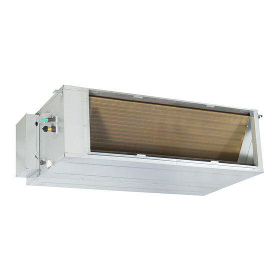
Electric control cabinet Drain hose Refrigerant connecting pipe Fig. 4.1 (applicable to KDI36, KDI42, KDI48 and KDI60) • Upon delivery, the package should be checked and any • Keep the unit upright in order to avoid damage should be reported immediately. -
Page 9: Indoor Unit Installation Instructions
This unit has been installed with an air intake pipe flange, but there is no air filter. (See Fig. 4.3 and Fig. 4.4) Supply air Return air (suspension position) 2 – 2 – Ø Ø Ø Ø NOTE: 14 groups all around NOTE: 12 groups all around Fig. 4.3 (applicable to KDI36, KDI42 and KDI48) Kaden Installation Manual | 9... - Page 10 NOTE: 16 groups all around (the same of the air inlet flange) Fig. 4.4 (applicable to KDI60 only) Table 4.1 Number Name Description Gas pipe connection 15.9 (KDI36, KDI42 and KDI48) 19 (KDI60) Ø Ø Liquid pipe connection Ø Drain pipe connection 25 ID Ø...
- Page 11 Supply air Return air Fig. 4.5 (applicable to KDI36, KDI42, KDI48 and KDI60) Table 4.2 Size of Air outlet opening size Air inlet opening size Outline dimension mounted lug (symmetry of air outlet opening) (symmetry of air inlet opening) Model KDI36, KDI42 &...
- Page 12 CAUTION NOTE: Confirm the minimum drain tilt is 1/100 or more. The unit body must be completely aligned with the hole. Ensure that the unit and the hole are the same size before moving on. 12 | Kaden Installation Manual...
- Page 13 5. If installed in a place like a meeting room where noise plate and repair the motor. is easy to be perceived, design isolation booth and internal duct underlayer to muffle the duct system and weaken the air encounter noise in the duct. Fig. 4.16 Kaden Installation Manual | 13...
- Page 14 Fig. 4.19 3. Repair it directly (only applicable to plastic scroll and fan wheel). • Take off the chassis assembly. • Take off the volute. • Take off the motor. Motor Volute Chassis assembly Fig. 4.20 14 | Kaden Installation Manual...
- Page 15 4. Separate the box and pull out the temperature sensing envelope/water pump line from the wire through hole in the electric control box. Cover plate Connecting plate Cover plate The sensor line or Water tray water pump line Through hole Chassis Kaden Installation Manual | 15...
-
Page 16: Outdoor Unit Installation
Fig. 5.3 • Be sure to remove any obstacles that may block air circulation. Strong wind • Make sure you refer to length specifications to ensure there is enough room for installation and maintenance. Fig. 5.1 16 | Kaden Installation Manual... -
Page 17: Outdoor Unit Specifications
Be sure to keep the unit unobstructed in at least two of the three directions (M, N, P). (See Fig. 5.7) 200mm from 600mm back wall above 300mm on left Fig. 5.5 600mm on right 2000mm in front Fig. 5.7 Fig. 5.6 Kaden Installation Manual | 17... -
Page 18: Drain Joint Installation
3. Place the protective wall cuff in the hole. This protects Seal the edges of the hole and will help seal it when you finish the installation process. Seal Drain joint Fig. 5.9 18 | Kaden Installation Manual... -
Page 19: Drainpipe Installation
This can lead to water leakage. Possible actions to avoid water leakage: 1. Disconnect power to drain pump. 2. Plumb drain pump spigot into gravity fed drain Lean over 1/50 Fig. 6.2 Kaden Installation Manual | 19... - Page 20 (a 1 minute lag is possible, depending on the length of the ≥100mm drain pipe). Check whether water leaks from the joints. Fig. 6.5 3. Turn off the air conditioner and put the cap back on. 20 | Kaden Installation Manual...
-
Page 21: Refrigerant Piping Connection
Table 7.1 The maximum length and drop height based on models. (Unit: metres) The indoor unit is installed higher than the outdoor unit Type of model Length of piping Maximum drop height Fig. 7.1 KDI36, KDI42, KDI48 and KDI60 Kaden Installation Manual | 21... -
Page 22: Refrigerant Piping Connection Instructions
3. Make sure that the pipe is cut at a perfect 90° angle. Refer to Fig. 7.3 for examples of good and bad cuts. The outdoor unit is installed higher than the indoor unit Fig. 7.2 ✓ ✕ ✕ ✕ 90° Oblique Rough Warped Fig. 7.3 22 | Kaden Installation Manual... - Page 23 Fig. 7.7 4. Remove PVC tape from ends of pipe when ready to perform flaring work. 8. Remove the flaring tool and flare form, then inspect the end of the pipe for cracks and even flaring. Kaden Installation Manual | 23...
-
Page 24: Note On Minimum Bend Radius
Ensure that you wrap insulation around the piping. Direct contact with the bare piping may result in burns or frostbite. • Make sure the pipe is properly connected. Over-tightening may damage the bell mouth and under-tightening may lead to leakage. 24 | Kaden Installation Manual... -
Page 25: Leak Testing And Evacuation
9. If the vacuum does not settle, repeat from Step 1 of Leak, pressure test and evacuations. If there is no change in system vacuum, unscrew the cap from the packed valve (high pressure valve). Low pressure Vacuum valve pump Fig. 8.1 Kaden Installation Manual | 25... -
Page 26: Preparations And Precautions
4. Using hexagonal wrench, fully open both the high pressure and low pressure valves. 5. Tighten valve caps on all three valves (service port, high pressure, low pressure) by hand. You may tighten it further using a torque wrench if needed. 26 | Kaden Installation Manual... -
Page 27: Wiring
220 – 220 – 220 – control board cover is properly installed. Failure to do so 240V 240V 240V 240V can cause overheating at the connection points, fire, and electrical shock. Circuit breaker/ fuse (A) Kaden Installation Manual | 27... - Page 28 The cable specifications are based on the assumption that a 40mm or more metal or plastic conduit is used with no more than three cables contained in a conduit and a voltage drop of 2%. Wire end 10mm Round crimp type terminal Sleeve 28 | Kaden Installation Manual...
-
Page 29: Signal Wiring Between Outdoor And Indoor Units
15cm of the wire. b. Strip the insulation from the ends of the wires. c. Using a wire crimper, crimp the u-lugs to the ends of the wires. Kaden Installation Manual | 29... - Page 30 The refrigerant circuit can become very hot. Keep the interconnection cable away from the copper tube. 4. Clamp down the cable with the cable clamp. The cable must not be loose or pull on the u-lugs. 5. Reattach the electric box cover. 30 | Kaden Installation Manual...
- Page 31 After 3 to 6 minutes, the air conditioning unit stops operating once automatic airflow adjustment has finished. – Press the CONFIRM button. – Press the CONFIRM button. The external static pressure settings is now complete. Kaden Installation Manual | 31...
- Page 32 STATIC PRESSURE (pa) SP1-M SP1-L SP2-M SP3-M 10 20 25 30 40 50 60 70 80 90 100 110 120 130 140 150 160 170 180 190 200 STATIC PRESSURE (pa) Note: SP2 M==SP1 H 32 | Kaden Installation Manual...
- Page 33 10 20 25 30 40 50 60 70 80 90 100 110 120 130 140 150 160 170 180 190 200 10 20 25 30 40 50 60 70 80 90 100 110 120 130 140 150 160 170 180 190 200 STATIC PRESSURE (pa) STATIC PRESSURE (pa) Note: SP2 M==SP1 H Kaden Installation Manual | 33...
-
Page 34: Electrical Checks
Measure grounding resistance by visual detection and with Risk of electric shock grounding resistance tester. Grounding resistance must be less than 4 Ω All wiring must comply with local and national electrical codes, and must be installed by a licensed electrician. 34 | Kaden Installation Manual... -
Page 35: Test Run
Ensure the manual buttons on the indoor unit works properly. e. Check to see that the drainage system is unimpeded and draining smoothly. Ensure there is no vibration or abnormal noise during operation. Kaden Installation Manual | 35... -
Page 36: Manual Operations
• OFF mode: When the panel is turned OFF, the unit turns off and the remote control is re-enabled. Manual Timer Infrared button indicator receiver display Operation Alarm indicator indicator PRE-DEF (pre-heating/defrost) indicator Fig. 12.1 36 | Kaden Installation Manual... -
Page 37: Error Codes
PC00 High/Low voltage protection Flash PC01 Compressor top overheating protection Flash PC02 Outdoor high/low pressure protection Flash PC03 Compressor drive error Flash PC04 Compressor low pressure protection Flash PC03 Outdoor IGBT sensor error Flash PC07 Kaden Installation Manual | 37... - Page 38 Notes 38 | Kaden Installation Manual...
- Page 39 Kaden Installation Manual | 39...
- Page 40 kadenair.com.au...
Need help?
Do you have a question about the KDI42 and is the answer not in the manual?
Questions and answers