
Related Manuals for Osram Regiolux CUA 2 Series


Summary of Contents for Osram Regiolux CUA 2 Series
- Page 1 CUA.-2 LED CUA./1200 1179 1000 CUA./1500 1479 1300 CUVA 6049 1100 100 DALI...
- Page 2 D / CH / A DALIeco Control F / B...
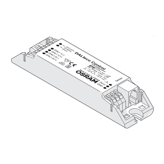
- Page 3 DALIeco Control 4,1 mm 220-240V; 50-60Hz; 40mA DALI 1(-) DALI 1(+) Sync DALI 2(-) DALI 2(+)
- Page 4 DALIeco Control 220-240V; 50-60Hz; 40mA DALI 1(-) DALI 1(+) Sync DALI 2(-) DALI 2(+) QTi DALI ECG CH-1 QTi DALI ECG CH-2...
- Page 5 DALIeco Control 220-240V; 50-60Hz; 40mA DALI 1(-) DALI 1(+) Sync DALI 2(-) DALI 2(+) QTi DALI ECG CH-1 QTi DALI ECG CH-2...
- Page 6 DALIeco Control 220-240V; 50-60Hz; 40mA DALI 1(-) DALI 1(+) Sync DALI 2(-) DALIeco LS/PD LI DALI 2(+) QTi DALI ECG CH-1 QTi DALI ECG CH-2 220-240V; 50-60Hz; 40mA DALI 1(-) DALI 1(+) Sync DALI 2(-) DALI 2(+)
- Page 7 DALIeco Control 220-240V; 50-60Hz; 40mA DALI 1(-) DALI 1(+) Sync DALI 2(-) DALIeco LS/PD LI DALI 2(+) QTi DALI ECG CH-1 QTi DALI ECG CH-2 DALI LS/PD LI...
- Page 8 DALIeco Control 220-240V; 50-60Hz; 40mA DALI 1(-) DALI 1(+) Sync DALI 2(-) DALI 2(+) DALI Professional push button coupler 220-240V; 50-60Hz; 40mA DALI 1(-) DALI 1(+) Sync DALI 2(-) DALI 2(+)
- Page 9 DALIeco Control Master Remote User Remote DALIeco Sensor select test Switch off delay Single Office (default) 1 sec 1 min 30 sec 3 min 5 min 10 min 15 min 30 min 60 min Macro Recorder Open-Plan Office PROG Holiday Resume Sensor select test...
- Page 10 DALIeco Control CH-2 30 % OFFSET DALI2 PROG CH-1 DALI1 REGULATED time Single Office 15 min. (default) STANDBY 30 % OFFSET CH-2 DALI2 PROG CH-1 DALI1 REGULATED 30 % OFFSET 30 % REGULATED time 15 min. 60 min. Open Plan Office...
- Page 11 DALIeco Control STANDBY STANDBY 100 % CH-2 DALI2 PROG CH-1 DALI1 10 % 10 % time 5 min. Corridor CH-2 30 % OFFSET DALI2 CH-1 PROG DALI1 REGULATED time Semi 15 min. Meetingroom / Classroom Auto...
- Page 12 DALIeco Control STANDBY 100 % CH-2 DALI2 PROG CH-1 DALI1 30 % time 15 min. 5 min. Sanitary Room STANDBY 100 % CH-2 DALI2 PROG CH-1 DALI1 50 % time 5 min. 1 min. Staircase...
-
Page 13: Table Of Contents
DALIeco Control D / CH / A DALIeco Control – Installation und Bedienung Inhaltsverzeichnis Schritt-für-Schritt System-Programmierung Allgemeine Hinweise ................. 13 Symbole und Abkürzungen in dieser Anleitung .......... 13 mittels Master Remote ................17 Bestimmungsgemäße Verwendung ............. 13 Programmiermodus (PROG-Modus) ............17 Funktionsmodi .................. -
Page 14: Allgemeine Hinweise
DALIeco Control D / CH / A Allgemeine Hinweise Montage und Installation 1.1 Symbole und Abkürzungen in dieser Anleitung 2.1 Abmessungen und Montagemaße • Listenpunkt, Aufzählung 2.2 Anschlussbelegung der Steuereinheit nummerierte Handlungsschritte mit vorgegebener Reihenfolge Verweis auf Abschnitt (z.B. 2.2) bzw. separate Anleitung (dann ohne Ziffern) Netzanschluss Bildverweis (z.B. -
Page 15: Vollautomatische Präsenz- Und Tageslichtabhängige Regelung
DALIeco Control D / CH / A Aktivieren der Zweitastersteuerung Anschluss von max. 4 Sensoren (3) via Y-Connector (4) und Sensorkabel (2) am Sensoranschluss • Gleichzeitiger VLP für 10s auf beide Taster (Beleuchtung blinkt zur Bestätigung) Steuereinheit (1). Anforderungen an Sensor- und Leuchten-Position: Tasterfunktionen (P1) •... -
Page 16: Einbindung Von Sensoren Über Die Dali Leitung
DALIeco Control D / CH / A Aktivieren der alternativen Funktion /Tastenbelegung der Tasterkoppler (2) Betriebsart mit endlichem Standby-Zustand (Open plan offi ce/Sanitary room /Staircase ) Programmiermodus über LP auf die „Prog“ Taste (5) der Fernbedienung starten Sensor Select über LP auf die Taste (10) der Fernbedienung aktivieren •... -
Page 17: Funktion Und Externe Komponenten
DALIeco Control D / CH / A Bedienung Funktion und externe Komponenten 3.1 Grundsätzliche Funktionsweise Beschreibung aller Tasten/LEDs der Master Remote und deren Funktionen, sowie Beschreibung Die Steuereinheit verändert/schaltet die Beleuchtung an Arbeitsplätzen, in Fluren und anderen aller Tasten/LED der User Remote und deren Grundfunktionen. gemeinsam genutzten Räumen in Abhängigkeit von nutzbarem Tageslicht und Anwesenheit/Be- 4.1 Fernbedienung Master Remote (und... -
Page 18: System Ein-/Ausschalten
DALIeco Control D / CH / A Schritt-für-Schritt System-Programmierung 4.2 Fernbedienung User Remote (und separate Anleitung) mittels Master Remote Tasten / LED (21) [ON/OFF] alle Leuchten ein/aus Programmierung bzw. Konfi guration erfolgen mittels Master Remote bzw. direkt am Sensor. (22) Signalisierung LED (grün/rot/orange) Bei Tastendruck Master Remote stets auf den entsprechenden Sensor richten. -
Page 19: Funktionsmodi
DALIeco Control D / CH / A 5.2 Funktionsmodi 5.5 Switch off delay (Nachlaufzeit) 14 . Schaltverhalten der vorkonfi gurierten Funktionsmodi: Diagramme Timer wird bis zum Verlassen des „ON“ Zustandes (Wechsel zu „STANDBY“ oder „OFF“) nach der letzten Präsenzerkennung eingestellt. In den Funktionsmodi „Corridor“, „Staircase“ u. „Sanitary“ •... -
Page 20: Testfunktion
DALIeco Control D / CH / A 5.10 Offset einstellen Tageslicht-Funktionen Der OFFSET (= Abstand von CH-2 zu CH-1) eines bestimmten Funktionsmodus einstellen. 100 h Taste [ON] • Vollautomatische Tageslichtregelung aktiv Taste [Offset] drücken (SP). Offset Burn-in PC modes Semi •... -
Page 21: Pc Modes
Taste keine Funktion. PC Software Mit der DALIeco PC Software können individuelle Funktionsprofi le und Parametrierungen erstellt, über USB auf der Master Remote gespeichert und anschließen über IR an das Steuergerät übertragen werden. Details und Software Download im Internet unter: www.osram.de/dalieco... -
Page 22: Unabhängige Bedienung Mehrerer Systeme
DALIeco Control D / CH / A Technische Daten 7.4 Unabhängige Bedienung mehrerer Systeme Anlernen der User Remote auf einen bestimmten, ausgewählten Empfänger, um eine unabhängi- Netzanschluss 220-240 V AC 50-60 Hz ge Bedienung mehrerer Systeme (maximal 15) im gleichen Raum zu ermöglichen. Eingang Taster Potenzialfreie Schließerkontakte, Tasten [CH-1... - Page 23 DALIeco Control DALIeco Control – Installation and Operation Contents Step-by-step system programming using Master Remote ...27 General....................23 Programming mode (PROG mode) ............27 Symbols and abbreviations in these instructions........23 Intended use ..................23 Function modes ................28 Auto setup ...................28 Mounting and installation ..............23 Manual setup ..................28 Dimensions and mounting dimensions ........23...
-
Page 24: General
DALIeco Control General Mounting and installation 1.1 Symbols and abbreviations in these instructions 2.1 Dimensions and mounting dimensions • Bullet point, listing 2.2 Connection allocation in the control unit Numbered steps with stipulated sequence Cross-reference to Section (e.g. 2.2) or separate instructions (but then without fi gures) Mains connection Figure cross-reference (e.g. -
Page 25: Fully Automatic Presence And Daylight-Dependent Control
DALIeco Control Push-buttons (P1) Requirements for sensor and luminaire position: • SP: Switching DALI CH-1 on and off (toggle function) • Entire workplace (to be monitored) is within monitoring area of the sensor. • LP: A Dimming DALI CH-1 up and down (toggle function) •... -
Page 26: Integrating Sensors Via The Dali Line
DALIeco Control Activating the alternative function / push-button allocation of the push-button coupler • If a push-button on pushbutton coupler input D is pressed, the control unit switches to the Start the programming mode via LP on "Prog" button (5) on the remote control OFF condition or the control unit remains in the OFF condition. -
Page 27: Function And External Components
DALIeco Control Operation Function and external components 3.1 Fundamental operating principle A description of all push-buttons/LEDs of the master remote and their functions and a descrip- The control unit changes/switches the lighting at workplaces, in corridors and other common tion of all push-buttons/LEDs of the user remote and their basic functions. rooms depending on the usable daylight and the presence/motion of persons. -
Page 28: Switch System On/Off
DALIeco Control Step-by-step system programming using Master Remote 4.2 User Remote remote control (and separate instructions) Push-buttons / LED Programming or confi guration is carried out using Master Remote or directly at the sensor. (21) [ON/OFF] All luminaires on/off When pressing the Master Remote push-button always point to the relevant sensor. (22) LED signalization (green/red/orange) Please note: (23) [1] Scene push-button 1... -
Page 29: Function Modes
DALIeco Control 5.2 Function modes 5.5 Switch off delay (overrun time) Switching behavior of the preconfi gured function modes: Diagrams 14 . The timer is set until exiting the "ON" condition (change to "STANDBY" or "OFF") according to the last detection of motion. In the function modes "Corridor", "Staircase" and "Sanitary", the •... -
Page 30: Daylight And Motion-Sensing Functions
DALIeco Control Daylight and motion-sensing functions 5.10 Setting offset The daylight and motion-sensing functions can be set for: Setting the OFFSET (=distance from CH-2 to CH-1) of a specifi c function mode. - jointly for directly connected sensors (PROG mode 5.1) - individually for directly connected sensors (sensor select 5.12) -
Page 31: Pc Modes
Individual function profi les and parameter settings can be created with the DALIeco PC Software, stored via USB on the Master Remote, then transferred via IR to the control unit. Details and software can be downloaded on the Internet at: www.osram.com/dalieco... -
Page 32: Independent Operation Of Several Systems
DALIeco Control Technical data 7.4 Independent operation of several systems Teaching of the User Remote to a specifi c selected receiver in order to permit independent Mains connection 220 – 240 V AC 50-60 Hz operation of several systems (maximum 15) in the same room. Push-button input Floating NO contacts, Simultaneously press push-buttons [CH-1... - Page 33 DALIeco Control DALIeco Control – Instalación y funcionamiento Índice Programación de sistema paso a paso Indicaciones generales ..............33 Símbolos y abreviaturas en el presente manual .........33 mediante el Master Remote .............37 Uso previsto..................33 Modo programación (modo PROG) ............37 Modos de funcionamiento ............38 Montaje e instalación ................33 Auto setup ...................38...
-
Page 34: Indicaciones Generales
DALIeco Control Indicaciones generales Montaje e instalación 1.1 Símbolos y abreviaturas en el presente manual 2.1 Dimensiones y medidas de montaje • Punto en la lista, enumeración 2.2 Asignación de conexiones de la unidad de control Pasos de procedimiento numerados con orden predeterminado Referencia a apartado (p. -
Page 35: Control Totalmente Automático En Función De La Luz Diurna Y De La Presencia
DALIeco Control Activación del sistema de control de dos botones 2.5 Conexión de sensor • Presione de forma prolongada y simultánea durante 10 s ambos pulsadores (los indicadores El sensor está diseñado para la integración de luminarias. Instalación y ajustes del sensor luminosos parpadean a modo de verificación) manual específi... -
Page 36: Integración De Sensores A Través De La Línea Dali
DALIeco Control Activación de la función alternativa / asignación de pulsadores del acoplador • Al accionar un pulsador en el acoplador de pulsadores de la entrada C, la unidad de control de pulsadores cambia al estado ON e inicia el tiempo de retardo de desconexión o vuelve a reiniciar el tiem- Iniciar el modo de programación mediante LP en la tecla "Prog"... -
Page 37: Función Y Componentes Externos
DALIeco Control Función y componentes externos Funcionamiento 3.1 Principio de funcionamiento básico Descripción de todas las teclas/LED del Master Remote y sus funciones, así como descripción La unidad de control modifi ca/conmuta la iluminación de lugares de trabajo, pasillos y otras de todas las teclas/LED del User Remote y sus funciones básicas. -
Page 38: Mando A Distancia User Remote Manual Específico)
DALIeco Control Programación de sistema paso a paso 4.2 Mando a distancia User Remote manual específi co) mediante el Master Remote Teclas / LED (21) [ON/OFF] todas las luminarias conectadas/desconectadas La programación o confi guración se lleva a cabo mediante el Master Remote o directamente en (22) Señalización LED (verde/rojo/naranja) el sensor. -
Page 39: Modos De Funcionamiento 8
DALIeco Control 5.2 Modos de funcionamiento 5.5 Switch off delay (tiempo de retardo de desconexión) Comportamiento de conmutación de los modos de función preconfi gurados: Diagramas El temporizador se ajusta tras la última detección de presencia hasta abandonar el estado "ON" hasta 14 . -
Page 40: Funciones De Luz Diurna Y De Presencia
DALIeco Control Funciones de luz diurna y de presencia 5.10 Ajustar Offset Las funciones de luz diurna y de presencia pueden ser seleccionadas: Ajustar el OFFSET (= distancia de CH-2 a CH-1) de un modo de funcionamiento determinado. - para sensores conectados directamente en conjunto (modo PROG 5.1) - para sensor conectado directamente individual (sensor select 5.12) -
Page 41: Pc Modes
El software DALIeco permite crear diferentes modos de funcionamiento y confi guraciones de parámetros. Estos pueden guardarse en el mando maestro mediante USB y transferirse a la unidad de control mediante IR. Puede descargar el software así como información relevante en línea: www.osram.com/dalieco... -
Page 42: Funcionamiento Independiente De Varios Sistemas
DALIeco Control Datos técnicos 7.4 Funcionamiento independiente de varios sistemas Programación del User Remote para un receptor determinado seleccionado, con el fi n de permi- Conexión a red 220 – 240 V CA 50-60 Hz tir un funcionamiento independiente de varios sistemas (máximo 15) en el mismo espacio. Entrada de pulsador Contactos normalmente abiertos, Pulsar simultáneamente las teclas [CH-1... - Page 43 DALIeco Control F / B DALIeco Control – Installation et utilisation Sommaire Système de programmation étape par étape Remarques générales ...............43 Symboles et abréviations de cette notice ...........43 via Master Remote ................47 Utilisation conforme ................43 Mode de programmation (mode PROG) ..........47 Modes de fonctionnement ............48 Montage et installation ..............43...
-
Page 44: Remarques Générales
DALIeco Control F / B Remarques générales Montage et installation 1.1 Symboles et abréviations de cette notice 2.1 Dimensions et mesures de montage • Point de liste, énumération 2.2 Occupation des branchements de l'unité de commande Étapes de procédure numérotées avec ordre prédéterminé Renvoi à... -
Page 45: Commande Entièrement Automatique De La Détection De Présence Et De L'éclairage De Jour Subordonné
DALIeco Control F / B Activation du système de commande à double touche 2.5 Raccordement du capteur • VLP simultanée pendant 10 sec. sur les deux touches (les indicateurs lumineux clignotent La cellule est prévue pour l'intégration de luminaires. Installation et réglage de la cellule notice séparée. -
Page 46: Intégration De Capteurs Par Ligne Dali
DALIeco Control F / B Activer la fonction alternative/occupation des boutons du coupleur (2) Mode de service avec état de veille à terme (Open plan offi ce / Sanitary room / Staircase) Démarrer le mode de programmation via LP avec la touche « Prog » (5) de la télécommande Activer Sensor Select via LP avec la touche «... -
Page 47: Fonction Et Composants Externes
DALIeco Control F / B Fonction et composants externes Utilisation 3.1 Fonctionnement de base Description de toutes les touches / tous les témoins lumineux du Master Remote et de leurs fonc- L'unité de commande modifi e/commute l'éclairage sur les postes de travail, dans les couloirs et autres tions, avec description de toutes les touches / tous les témoins lumineux du User Remote et leurs espaces communs en fonction de la lumière du jour et de la présence/du mouvement de personnes. -
Page 48: Télécommande Master User (Et Notice Séparée)
DALIeco Control F / B Système de programmation étape par étape 4.2 Télécommande Master User notice séparée) via Master Remote Touches/LED (21) [ON/OFF] Tous les éclairages on/off La programmation du système est effectuée via Master Remote ou directement sur la cellule. (22) Signalisation LED (vert/rouge/orange) En appuyant sur la touche Master Remote, toujours pointer vers la cellule correspondante. -
Page 49: Modes De Fonctionnement 8
DALIeco Control F / B 5.5 Switch off delay (temporisation) 5.2 Modes de fonctionnement Comportement de commutation des modes de fonctionnement préconfi gurés : Diagrammes Minuterie active jusqu'à la fi n de l'état « ON » (passage à « stand-by » ou « OFF ») après la jusqu'à... -
Page 50: Fonctions Lumière Du Jour Et Présence
DALIeco Control F / B Fonctions lumière du jour et présence 5.10 Régler l'offset Les fonctions lumière du jour et présence : Régler l'OFFSET (= distance de CH-2 à CH-1) d'un mode de fonctionnement particulier. - communément pour des capteurs raccordés (mode PROG 5.1) - individuellement pour des capteurs directement raccordés (Sensor select 5.12) -
Page 51: Modes Pc
Activer le mode de programmation en appuyant de façon Des informations détaillées et le logiciel peuvent être téléchargés sur le site Internet : 100 h prolongée sur la touche [Prog] www.osram.com/dalieco Offset Burn-in PC modes Actionner la touche [PC1] ou [PC2] pour démarrer le proces- sus d'envoi Utilisation du système avec User Remote... -
Page 52: Utilisation Indépendante De Plusieurs Systèmes
DALIeco Control F / B Caractéristiques techniques 7.4 Utilisation indépendante de plusieurs systèmes Adapter l'User Remote à un récepteur précis sélectionné pour une utilisation indépendante de Raccordement électrique 220 – 240 V CA 50-60 Hz plusieurs systèmes (maximal 15) dans une même pièce. Entrée boutons Contacts de fermeture sans potentiel, Appuyer en même temps sur [CH-1... - Page 53 DALIeco Control DALIeco Control – Installazione e uso Indice Programmazione del sistema passo a passo Indicazioni generali................53 Simboli e abbreviazioni delle presenti istruzioni........53 con Master Remote ................57 Uso conforme a destinazione ..............53 Modalità di programmazione (modalità PROG)........57 Modalità di funzionamento ............58 Montaggio e installazione ..............53 Auto setup ...................58...
-
Page 54: Indicazioni Generali
DALIeco Control Indicazioni generali Montaggio e installazione 1.1 Simboli e abbreviazioni delle presenti istruzioni 2.1 Dimensioni e misure di montaggio • Voce di un elenco, enumerazione 2.2 Assegnazione dei collegamenti dell'unità di comando Fase di lavoro numerata con sequenza prestabilita Rimando a sezione (ad es. -
Page 55: Completamente Automatizzato E Comando Dipendente Dalla Luce Diurna
DALIeco Control Attivazione del sistema di controllo a due pulsanti 2.5 Collegamento sensore VLP simultaneo per 10s su entrambi i pulsanti (controllare gli indicatori luminosi lampeggianti) Il sensore è destinato all'integrazione della lampada. Installazione e impostazioni del sensore istruzioni separate. Pulsanti (P1) Collegamento di max. -
Page 56: Inclusione Dei Sensori Tramite Linea Dali
DALIeco Control Attivazione della funzione alternativa / assegnazione pulsanti degli • All'azionamento di un pulsante nell'accoppiatore pulsante dell'ingresso D, la centralina passa accoppiatori pulsante allo stato OFF o rimane nello stato OFF. Avviare la modalità di programmazione mediante LP sul tasto "Prog" (5) del telecomando (2) Modalità... -
Page 57: Funzione E Componenti Esterni
DALIeco Control Funzione e componenti esterni 3.1 Modo di funzionamento di principio Descrizione di tutti i pulsanti/LED del Master Remote e delle relative funzioni nonché descrizione L'unità di comando cambia/commuta l'illuminazione in posti di lavoro, corridoi e altri spazi di tutti i pulsanti/LED dell'User Remote e delle loro funzioni di base. comuni in funzione della luce diurna utile e della presenza/del movimento delle persone. -
Page 58: Telecomando User Remote Istruzioni Separate)
DALIeco Control Programmazione del sistema passo a passo 4.2 Telecomando User Remote istruzioni separate) con Master Remote Tasti / LED (21) [ON/OFF] tutte le lampade on/off La programmazione o confi gurazione avvengono per mezzo del Master Remote o direttamente (22) segnalazione LED (verde/rosso/arancione) dal sensore. -
Page 59: Modalità Di Funzionamento
DALIeco Control 5.5 Switch off delay (ritardo di spegnimento) 5.2 Modalità di funzionamento Comportamento di commutazione delle modalità di funzionamento preconfi gurate: Diagrammi da Il timer viene impostato dopo l'ultimo rilevamento della presenza fi no all'uscita dallo stato "ON" 14 . (passaggio a "STANDBY"... -
Page 60: Funzioni Luce Diurna E Presenza
DALIeco Control Funzioni luce diurna e presenza 5.10 Regolazione dell'offset Le funzioni luce diurna e presenza possono essere impostate: Regolare l'OFFSET (= intervallo da CH-2 a CH-1) di una determinata modalità di funzionamento. - per i sensori collegati direttamente (modalità PROG 5.1) 100 h - individualmente per i sensori collegati direttamente (Sensor select... -
Page 61: Pc Modes
I profi li di funzionamento singoli e l'impostazione dei parametri possono essere creati con DALIeco PC Software, archiviati tramite USB sul Master Remote, quindi trasferiti tramite IR all'unità di controllo. Maggiori informazioni e il software sono disponibili all'indirizzo Internet: www.osram.com/dalieco... -
Page 62: Uso Indipendente Di Più Sistemi
DALIeco Control Dati tecnici 7.4 Uso indipendente di più sistemi Sintonizzazione dell'User Remote su un determinato ricevitore selezionato, in modo da consenti- Collegamento alla rete elettrica 220 – 240 V AC 50-60 Hz re l'uso indipendente di più sistemi (massimo 15) nello stesso ambiente. Ingresso pulsante Contatti di chiusura a potenziale zero, Premere contemporaneamente i tasti [CH-1... - Page 63 DE / CH / A F / B OSRAM GmbH Steinerne Furt 62 86167 Augsburg C10449064 Germany G10576785 www.osram.com 29.09.15...
- Page 64 Sicherheitshinweise Safety Information Consignes de sécurité Allgemeine Sicherheitshinweise General Safety Information Consignes générales de sécurité • Montage, Inbetriebnahme und Wartung nur durch • Installation, commissioning and maintenance only by • Montage, mise en service et maintenance uniquement par un quali昀椀ed electrician. Elektrofachkraft.
- Page 65 Zasady bezpieczeństwa Advertencias de seguridad Avvertenze sulla sicurezza Ogólne zasady bezpieczeństwa Advertencias de seguridad generales Avvertenze generali sulla sicurezza • Prace związane z montażem, uruchomieniem i konserwacją może • El montaje, la puesta en funcionamiento y el mantenimiento debe- • Il montaggio, l‘impiego e la manutenzione devono essere wykonywać...
Need help?
Do you have a question about the Regiolux CUA 2 Series and is the answer not in the manual?
Questions and answers