Table of Contents
Advertisement
Available languages
Available languages
Advertisement
Table of Contents

Related Manuals for Osram Butler XT2


Summary of Contents for Osram Butler XT2
- Page 1 Butler XT2 Setup Manual...
- Page 2 Butler XT2 Setup Manual Edition/Ausgabe: 23.12.2016 Published by/Herausgegeben von: OSRAM GmbH BU Lighting Solutions Karl Schurz-Strasse 38 Paderborn, Germany ©2016, OSRAM GmbH All rights reserved/Alle Rechte vorbehalten...
-
Page 3: Table Of Contents
Using the standalone web interface ........... 15 Online configuration with Programmer ........... 18 Network parameters ................20 Connecting more than one Butler XT2 ..........22 Standalone control via web browser ............23 Adjusting the internal Real Time Clock ..........23 Firmware update .................. - Page 4 Betriebsanzeigen ................38 Standlone-Konfiguration ................ 39 Online-Konfiguration ................42 Netzwerk-Parameter ................44 Anschließen von mehreren Butler XT2 ..........46 Standalone-Steuerung über Webbrowser ..........47 Justierung der internen Echtzeituhr ............47 Firmware-Update ................... 48 Action Pad und Mobile Action Pad ............48...
- Page 5 Setup Manual - Butler XT2 Technische Daten ................... 49 Allgemeine Daten ................49 DMX ....................50 e:bus ....................50 RS-232 ....................50 Problemanalyse ..................51 Software .................... 51 Hardware ................... 52 Appendix ..............53 Change log ..................... 54 Dimensions/Abmessungen..............56 Connection diagram/Verbindungsbeispiel ..........57...
-
Page 6: English
Setup Manual - Butler XT2 English... -
Page 7: Security Instructions
Setup Manual - Butler XT2 Security instructions The product must only be installed and put into operation by a qualified electrician. The applicable safety regulations and accident prevention regulations must be observed. Otherwise the unit may be damaged. Only work on the product when it is de-energized to prevent electrical shocks. -
Page 8: Delivery Content
AA611810135 Transport Only transport the Butler XT2 in its original packaging. This protects the device from damage. Only unpack the at its installation location. To protect the device against condensation water, unpack it and wait until all moisture remaining in the Butler XT2 has evaporated. -
Page 9: Connector Panel
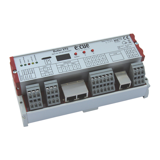
Setup Manual - Butler XT2 Connector panel Power The Butler XT2 must be powered by an external AC/DC Power Supply. Power over Ethernet and Power over DMX are not supported. Always use an external power supply. The power supply must meet the following requirements: y Output Voltage: 24 V DC y Output Current: >= 1.4 A... - Page 10 Setup Manual - Butler XT2 Connecting the clamp terminals Butler XT2 terminals Use an electrostatic sensitive screw driver Put the screw driver into one of the small Push the screw driver into e slot and slots above the contact you want to con- pull it upwards.
-
Page 11: Digital Inputs
The Butler XT is now ready release the screw driver. to use. Digital inputs The Butler XT2 offers eight configurable optically Dig. interface isolated digital inputs for connectivity to separate systems/sensors. See connection diagram on the right below for details. -
Page 12: E:bus
Network Configuration Guide, available at www.ecue.com/download for more details about e:bus. RS-232 For communication between different systems the Butler XT2 offers an RS-232 interface (configuration: 9600 baud, 8 databits, no parity, 1 stopbit). Format: [CMD1] [CMD2] [Param1 (3 digits)] {[Param2 (3 digits) ]} 0x0d 0x0a Parameters always must have 3 Characters with leading 0s. -
Page 13: Micro Sd Card
Trigger Label for Label Index sss, e.g. TL001 Micro SD card The Butler XT2 comes with a micro SD card and cannot operate if no micro SD card is present. A typical show file incl. configuration files is not bigger than a few Megabytes, the Butler XT2 is designed to work with such typical show files. -
Page 14: Interface Elements
Button System and “a” in combination: When a blinking is displayed, release the buttons. The Butler XT2 will be reset to factory state. This includes the IP address. Buttons a and b For the buttons a and b you can assign functions with the Lighting Application Suite, depending on the operation mode. -
Page 15: Standalone Configuration
Loader mode Display Description The Butler XT2 is in loader mode and waits for a firmware update. LOAd Standalone configuration The Butler XT2 can either be configured in standalone mode without the Lighting Application Suite and only with a web browser and a PC, or it can be setup in online mode with the Lighting Application Suite. -
Page 16: Using The Standalone Web Interface
Connect the Butler XT2 with power and via a standard LAN patch cable over an Ethernet switch to the server (LCE or PC). If you want to connect the Butler XT2 without Ethernet switch to the server use a so called cross cable, as not all Ethernet interfaces support automatic RX/TX detection. - Page 17 Setup Manual - Butler XT2 To change the configuration, click the upper Configure button and enter the pass- word. The default password is “ecue”, it can be changed during configuration. Click Enter and the main configuration dialogue gets displayed. Change the parameters (explained in the following chapter) and click Submit.
-
Page 18: Online Configuration With Programmer
Butler XT2. The Butler XT2 should become visible. Click on the Butler XT2 line in the Network display, this opens the device configura- tion dialog. Here you can set all driver properties of the Butler XT2. - Page 19 Apply the changes with the Ok button If no show is exported to the Butler XT2, e. g. when the Butler XT2 is in factory state, no DST information and master/slave settings are available. As soon as a show has been downloaded, correct DST...
-
Page 20: Network Parameters
Setup Manual - Butler XT2 Network parameters Device Basics Device Name The device will be displayed with this name in the e:cue programmer. IP address The IP address of the device (default: 192.168.123.1) Subnet Mask The netmask of the device (Default: 255.255.255.0) - Page 21 Setup Manual - Butler XT2 To add the Butler XT2 to the Programmer configuration start the Device Manager. Execute the Automatic Setup Wizard. The Butler XT2 will be found and displayed: Set the checkmark for the Butler XT2 to add it to your setup or click the Select button.
-
Page 22: Connecting More Than One Butler Xt2
IP-address by factory default. If they are connected simultaneously an IP-address conflict will occur and configuration is not possible. Instead, connect the Butlers XT2 one at a time. Connect the first Butler XT2 and assign a new IP-address to the device (e.g. 192.168.123.11). Repeat this sequence until all devices have been assigned with an individual IP-address. -
Page 23: Standalone Control Via Web Browser
Standalone control via web browser In standalone mode it is possible the Butler XT2 via a web browser. Connect a PC-based system to the e:net interface like shown in the chapter » Using the stan- dalone web interface«. Start the browser and enter the IP address of the Butler XT2 as URL. -
Page 24: Firmware Update
The new firmware is available now. Action Pad and Mobile Action Pad The Butler XT2 can be controlled from a remote instance like a PC, an iOS device like iPhone or iPad, or via Android devices. See the »System Manual« for the Light-... -
Page 25: Technical Specifications
Setup Manual - Butler XT2 Technical specifications General specifications Dimensions 177 x 60 x 75 mm/7 x 2.4 x 3 inch Weight 0.4 kg/0.88 lbs Power 12 … 24 V DC via terminals Operating/storage temp. 0 … 40 °C/32 … 104 °F Operating/storage hum. - Page 26 Transfer rate & Configuration 9600 baud, 8 bits, no parity, 1 stopbit Optical isolation yes, 3 kV The Butler XT2 is certified according to: EN 55022, EN 55024, EN 60950 Conforms to ANSi/UL Std. 60950-1. Certified to CAN/CSA Std. C22.2#60950-1.
-
Page 27: Problem Analysis
Patchelor Address assigned? fixed address. Also, the first three parts of the IP address must be the same IP as for the Butler XT2. Example: 192.168.123. xxx. Butler XT2 not online or Programmer/Patchelor e:net interface included IP... -
Page 28: Hardware
Setup Manual - Butler XT2 Butler XT2 configuration Butler XT2 is bound in Remove Butler XT2 in dialog in network status Programmer and “Enable Device Manager or disable window cannot be opened Driver” is set. driver is Device Manager’s configuration dialog. -
Page 29: Deutsch
Setup Manual - Butler XT2 Deutsch... -
Page 30: Sicherheitshinweise
Setup Manual - Butler XT2 Sicherheitshinweise Das Produkt darf nur von einer Elektrofachkraft installiert und in Betrieb genommen werden. Die geltenden Sicherheits- und Unfallverhütungs- vorschriften sind zu beachten. Arbeiten an dem Produkt nur im spannungsfreien Zustand durchführen. Anderenfalls kann zu elektrischen Schocks kommen oder das Gerät wird beschädigt. -
Page 31: Lieferumfang
RJ45 auf XLR5p Adapterkabel AA611810135 Transport Transportieren Sie den Butler XT2 nur in seiner originalen Verpackung um Schäden zu vermeiden. Entpacken Sie den Butler XT2 nur am Installationsort. Um Schäden bei Wechsel von Kälte zu Wärme durch Kondensationswasser zu verhindern, warten Sie nach dem Auspacken, bis das Gerät die Temperatur am Installationsort... -
Page 32: Anschlussfeld
Setup Manual - Butler XT2 Anschlussfeld Stromversorgung Der ButlerXT2 wird von einem externen Netzteil versorgt. Die Speisung über Ethernet oder DMX wie beim Butler XT ist nicht mehr möglich. Die Stromversorgung über Netzteil muss folgende Bedingungen erfüllen: y Ausgangsspannung 24 V= y Ausgangsstrom: >= 1.3 A... - Page 33 Setup Manual - Butler XT2 Anschluss der Klemmverbindungen Butler XT2-Anschlüsse Benutzen Sie einen isolierten Schraubendreher. Bringen Sie den Schraubendreher Zum Öffnen des Kontaktes drücken Sie in den oberen Schlitz des jeweiligen den Schraubendreher nach oben. Kontaktes.
-
Page 34: Digitale Eingänge
Versichern Sie sich, dass der Anschluss führen Sie den Anschlussdraht in den auch wirklich fest sitzt. Kontakt ein. Digitale Eingänge Der Butler XT2 verfügt über acht konfigurierbare, Dig. interface optoelektrisch isolierte Eingänge zum Anschluss von Fremdsystemen oder Sensoren. Der Eingangsspannungs-Bereich für die digitalen Eingänge beträgt 9 bis... -
Page 35: E:bus
Setup Manual - Butler XT2 pin no. signal DMX- DMX+ VCC in e:bus e:bus ist ein Zweidraht-Bussystem, bei dem die Verbindungen über Klemman- schlüse hergestellt werden. Diese Verbindungstechnik ist ausgesprochen flexibel und robust. Nicht nur ist e:bus in verschiedensten Topologien einsetzbar, sondern es gibt auch keine festgelegte Polarität. -
Page 36: Micro Sd-Karte
SD-Karte nicht betrieben werden. Ein typisches Showfile inkl. Konfigurationsdateien ist normalerweise nicht größer als einige Megabytes und auf solche Shows ist der Betrieb des Butler XT2 ausgelegt. Dennoch ist es möglich Shows zu erstellen welche die Kapazität überschreiten. Im Folgenden ein paar Hinweise: - Je größer die Show, desto größer werden die Zugriffszeiten zu den Cuelist... -
Page 37: System-Taster
Im Normalbetrieb: Lang drücken: (ca. 4 Sekunden): Sobald ein blinkendes angezeigt wird, Taster los lassen und der Butler XT2 wird neu gestartet. Taster System und Taster “a” zusammen: Ein blinkendes wird angezeigt. Taster los lassen und der Butler XT2 wird auf Werkseinstellungen zurück gesetzt. -
Page 38: Betriebsanzeigen
System neu, falls der Fehler wieder auftritt, verständigen Sie den Service. Ein blinkendes S zeigt Standby an, Butler XT2 in Standalone- Modus, aber es läuft keine Cuelist oder es sind keine Cuelists verfügbar. Loader-Modus Display Description Der Butler XT2 ist im Loader-Modus und wartet auf eine neue LOAd Firmware. -
Page 39: Standlone-Konfiguration
Setup Manual - Butler XT2 Standlone-Konfiguration Der Butler XT2 kann entweder im standalone Modus ohne Verbindung zur Lighting Application Suite mit mit einem Webbrowser und PC oder im Online Modus mit Lighting Application Suite betrieben werden. Für die Konfiguration im standalone Modus werden die Werkseinstellungen des Butler XT2 empfohlen. - Page 40 Setup Manual - Butler XT2 Zum Ändern der Konfiguration clicken Sie Configure und geben Sie das Passwort ein. Das Passwort ab Werk ist “ecue”, es kann später geändert werden. Clicken Sie Enter und der Hauptdialog wird angezeigt. Stellen Sie die Netzwerk-...
- Page 41 Setup Manual - Butler XT2 Eine Erklärung der Parameter finden Sie im nächsten Kapitel.
-
Page 42: Online-Konfiguration
Setup Manual - Butler XT2 Online-Konfiguration Verbinden Sie den Butler XT2 über einen Switch mit einem System, auf dem die e:cue Lighting Application Suite installiert ist. Starten Sie den Programmer. Wählen Sie den den Network-Reiter im Status-Fenster links oben. Die verbundenen Butler XT2s sollten dort angezeigt werden. - Page 43 Mit Ok werden die Änderungen bestätigt und die neue Konfiguration wird auf den Butler XT2 übertragen. Falls noch keine Show auf den Butler XT2 übertragen wurde, kön- nen die Sommerzeit-Informationen nicht verwendet werden. Gleich- es gilt für die Master-/Slave-Einstellungen. Beim ersten Laden einer...
-
Page 44: Netzwerk-Parameter
Setup Manual - Butler XT2 Netzwerk-Parameter Device Basics Device Name Der Name, mit dem der Butler XT2 im Programmer angezeigt wird. IP address Die IP-Adresse des Systems (Default: 192.168.123.1). Subnet Mask Netmask für die Verbindung (Default: 255.255.255.0). Gateway address Die Adresse des IP-Gateways (kein Gateway). - Page 45 Starten Sie den Automatic Setup Wizard. Der Butler XT2 wird gefunden und angezeigt. Setzen Sie die Auswahl für den Butler XT2, um ihn der Konfiguration hinzu zu fügen. Löschen Sie die Auswahl für die e:bus- Geräte, falls keine e:bus-Geräte verwendet werden.
-
Page 46: Anschließen Von Mehreren Butler Xt2
Anschließen von mehreren Butler XT2 Falls Sie mehr als einen Butler XT2 neu anschließen wollen, muss ein Butler XT2 nach dem anderen konfiguriert werden. Schließen Sie nicht mehrere Butler XT2 gleichzeitig an, da die Systeme ab Werk mit der gleichen IP-Adresse versehen sind und so Adresskonflikte im Netz auftreten und die Konfiguration nicht möglich ist. -
Page 47: Standalone-Steuerung Über Webbrowser
Setup Manual - Butler XT2 Standalone-Steuerung über Webbrowser Im Standalone-Betrieb kann der Butler XT2 auch über einen Webbrowser gesteuert werden. Schließen Sie dazu einen PC mit einem Webbrowser an wie im Kapitel »Standalone-Konfiguration« gezeigt. Geben Sie die IP-Adresse des Butler XT2 als URL im Browser an. -
Page 48: Firmware-Update
Setup Manual - Butler XT2 Firmware-Update Um eine neue Firmware auf den Butler XT2 zu laden gehen Sie wie folgt vor: y Starten Sie den Patchelor der e:cue Lighting Application Suite. y In der Liste gefundener Geräte wählen Sie den entsprechenden Butler XT2. -
Page 49: Technische Daten
Setup Manual - Butler XT2 Technische Daten Allgemeine Daten Abmessungen 177 x 60 x 75 mm Gewicht 0,4 kg Stromversorgung 12 ... 24 V= über Klemmen Betriebs-/Lagertemperatur 0 ... 40 °C Betriebs-/Lagerfeuchte 0 ... 80%, nicht kondensierend Schutzklasse IP20, SELV Gehäuse... -
Page 50: Dmx
Setup Manual - Butler XT2 Anzahl Ausgänge 2 DMX-Universen, 1024 Kanäle Kurzschlussschutz ja, selbstzurücksetzend Überspannungsschutz DMX-Betrieb Acc. DMX-512A Standard Optoelektr. isoliert ja, 3 kV max. e:bus Anzahl Ausgänge 1 x Klemmen Kurzsschlussschutz ja, selbstzurücksetzend Überspannungsschutz Max. Ausgangsstrom 1,2 A Max. Anz. Glass Touch Optoelektr. -
Page 51: Problemanalyse
Setup Manual - Butler XT2 Problemanalyse Software Problem Überprüfung Grund Butler XT2 nicht online Ist eine Netzwerkkarte mit Die IP-Adresse des Rech- oder nicht sichtbar im fester Adresse zugew- ners muss fest vergeben Programmer/Patchelor iesen? sein. Ebenso müssen die ersten drei Bestandteile... -
Page 52: Hardware
Setup Manual - Butler XT2 Der Konfigurations-Dialog Der Butler XT2 ist durch Entfernen Sie den Butler in der Netzwerk-Übersicht den Programmer belegt. XT2 aus der Konfiguration lässt sich nicht öffnen des Programmer oder schalten Sie den Treiber im Device Manager aus. -
Page 53: Appendix
Setup Manual - Butler XT2 Appendix... -
Page 54: Change Log
Setup Manual - Butler XT2 Change log Firmware Build Changes 2.0.3308 2016-09-19 NEW: HTTP ERROR 404 included NEW: RTC adjustments included FIX: respond with random timeout to who is 2.0.1527 2013-08-16 there requests - better load ballance in large installations New: Option support for HTTP access Control 2.0.1511... -
Page 55: Dimensions/Abmessungen
Setup Manual - Butler XT2 Dimensions/Abmessungen All dimensions in mm/in Alle Abmessungen in mm/in 59.5 mm/2.34 inch... -
Page 56: Connection Diagram/Verbindungsbeispiel
Setup Manual - Butler XT2 Connection diagram/Verbindungsbeispiel... - Page 57 Setup Manual - Butler XT2 Notes...
-
Page 58: Notes
Setup Manual - Butler XT2 Notes... - Page 59 Setup Manual - Butler XT2...
- Page 60 For more information visit www.ecue.com...
Need help?
Do you have a question about the Butler XT2 and is the answer not in the manual?
Questions and answers