
Related Manuals for Osram DALI ACU BT


Summary of Contents for Osram DALI ACU BT
- Page 1 11/2021 Installation guide and mounting instructions OSRAM BT controls Light is OSRAM...
-
Page 2: Table Of Contents
OSRAM BT controls | Contents Contents 1 BT controls 2 Wiring diagrams 2.1 DALI ACU BT 2.2 DALIeco BT 2.3 DALIeco BT RTC 3 Limitations on connectable devices 4 Mounting instructions for BT controls 4.1 Radio optimization 4.2 Guidelines for control placement to optimize the stability and effective range of the BT connection 4.3 Best practice examples... -
Page 3: Bt Controls
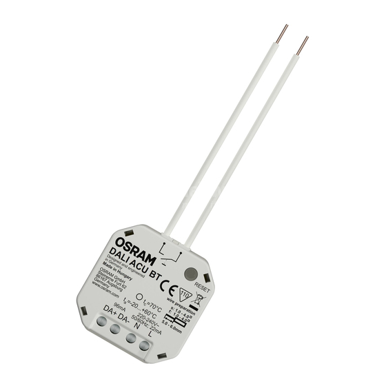
All three hardware types of BT controls feature the same electrical parameters: Electrical parameters Value 220-240 V; 50/60 Hz 0.3-3 W -20 … +60 °C IP rating IP20 Max. DALI load 32 ECGs + 4 OSRAM DALI sensors or DALI pushbutton couplers 96 mA... -
Page 4: Wiring Diagrams
OSRAM BT controls | Wiring diagrams 2 Wiring diagrams 2.1 DALI ACU BT 2.2 DALIeco BT 2.2 DALIeco BT 2.2 DALIeco BT 2.2 DALIeco BT 2.3 DALIeco BT RTC... -
Page 5: Limitations On Connectable Devices
OSRAM BT controls | Limitations on connectable devices 3 Limitations on connectable devices Relevant for all three BT controls: DALI ACU BT, DALIeco BT and DALIeco BT RTC (with integrated real-time clock) Number of Number of Max. number of Max. number of... -
Page 6: Mounting Instructions For Bt Controls
The wireless Bluetooth Low Energy (BLE) interface is based on the Bluetooth 4.0 protocol. Connectivity range: ≤15 m DALIeco BT, DALIeco BT RTC DALI ACU BT 1) Do not place any mains voltage or LED supply wires within or close to this area 2) Recommended minimal distance to metal parts 3) Placement of integrated radio transmitter antenna 4.2 Guidelines for control placement to optimize the stability and effective range of the BT connection... -
Page 7: Best Practice Examples
OSRAM BT controls | Mounting instructions for BT controls 4.3 Best practice examples Floor-standing luminaire mounting A: Lumimnaire head B: Transition area from pole to head C: Pole General mounting rules: Metal surrounding the antenna Non-metallic surrounding material ... -
Page 8: Function Validation
The check should be done using: — The OSRAM BT app and a mobile device for testing the range of the mobile device to the BT the antenna — In case of Swarm function: A second BT control unit to test the point-to-point range between Swarm participants Please note: The result of the validation is not an index of replicability in all environments and application situations. -
Page 9: Mounting Instruction For Connectable Dali Sensors
OSRAM BT controls | Mounting instructions for connectable DALI sensors 5 Mounting instructions for connectable DALI sensors 5.1 Sensors and networking 1) LED display 2) Sensor button (recessed in housing) 3) Presence sensor 4) Shutter mechanism (for setting the presence detection range) -
Page 10: Guidelines For Sensor Placement To Optimize The Functionality And The Detection Area
OSRAM BT controls | Mounting instructions for connectable DALI sensors B: Cover (2) for installing the sensor internally The cover is placed on the sensor housing. If the sensor is in the correct mounting position, the raised surface of the cover will sit fl ush in the luminaire opening (1). - Page 11 OSRAM BT controls | Mounting instructions for connectable DALI sensors Keep a distance between each of the sensor-controlled luminaires of at least the same distance as the installa- tion height measured from the floor to the sensor. > h Use the integrated shutter mechanism to adjust the detection pattern according to your individual needs.
- Page 12 OSRAM GmbH OSRAM Lighting Middle East FZE OSRAM OOO Russia DS Headquarters Germany Dubai – United Arab Emirates Phone: +7 (499) 649-7070 Phone: +49 89 6213-0 Phone: +971 4 523 1777 E-mail: ds-russia@osram.com E-mail: contact@osram.com E-mail: ds-mea@osram.com OSRAM Romania S.R.L.
Need help?
Do you have a question about the DALI ACU BT and is the answer not in the manual?
Questions and answers