Table of Contents
Advertisement
Available languages
Available languages
Quick Links
Istruzioni per l' installazione
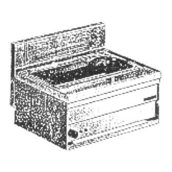
BAGNOMARIA
IT
CH
e l' uso
A SECCO
Aufstellungs und
DE
AT
CH
WARMHALTEWANNE
Bidienungsanweisungen
Instruction puor l' installation
FR
BE
BAIN MARIE A SEC
et l' emploi
GB
IE
Instructions
DRY WARMING UP
for the installation and use
Modello Typ Modéle Model
BS-1EM BS-61EM BS-62EM
NO.DOC. BS-1EM BS-61EM BS-62EM
EDIZIONE 03.02
Advertisement
Chapters
Table of Contents

Related Manuals for Lotus BS-1EM


Summary of Contents for Lotus BS-1EM
- Page 1 A SECCO Aufstellungs und WARMHALTEWANNE Bidienungsanweisungen Instruction puor l’ installation BAIN MARIE A SEC et l’ emploi Instructions DRY WARMING UP for the installation and use Modello Typ Modéle Model BS-1EM BS-61EM BS-62EM NO.DOC. BS-1EM BS-61EM BS-62EM EDIZIONE 03.02...
- Page 2 Pag. Seite Page Page...
-
Page 3: Table Of Contents
INDICE ISTRUZIONI PER L’ INSTALLAZIONE ..................... 4 DATI TECNICI E RAPPRESENTAZIONE SCHEMATICA ................4 SCHEMA ELETTRICO .......................... 4 MESSA IN OPERA ..........................5 DISPOSIZIONI DI LEGGE, REGOLE TECNICHE E DIRETTIVE ..............5 INSTALLAZIONE ..........................5 ALLACCIAMENTO ELETTRICO......................5 EQUIPOTENZIALE ..........................5 MESSA IN FUNZIONE ........................ -
Page 4: Istruzioni Per L' Installazione
3mm. DATI ELETTRICI Modelli Alimentazione Potenza max Cavo di alimentazione BS-1EM BS-61EM 230 V 0,83 KW 3x0,75 mm2 BS-62EM 230 V 0,83 KW... -
Page 5: Messa In Opera
(vedi punto 1.1). Passare il cavo attraverso il passacavo ed il pressacavo, collegare i conduttori nel corrispondente morsetto della morsettiera e fissarli. Il conduttore di terra deve essere più lungo degli altri, in modo che, in caso di rottura del fermacavo, questo si stacca dopo i cavi della tensione. BS-1EM BS-61EM BS-62EM EQUIPOTENZIALE L’... -
Page 6: Messa In Funzione
30°C e i 90°C, si accendono le spie (B) e (C). La lampada spia (B) indica che l’ apparecchio è sotto tensione. L’ accensione della lampada spia (C) segnala il funzionamento dell’ elemento riscaldante, il suo spegnimento indica il raggiungimento della temperatura. Per spegnere l’ apparecchio, rimettere la manopola (A) in posizione (O). BS-1EM BS-62EM BS-61EM PULIZIA E CURA Attenzione: durante la pulizia non lavare esternamente l’... - Page 7 INHALTSVERZEICHNIS AUFSTELLUNGSANWEISUNG ......................8 ANGABEN ZUM GERÄT UND SCHEMATISCHE DARSTELLUNG ............. 8 SCHALTPLAN ............................. 8 AUFSTELLUNG ........................... 9 RECHTSVERORDNUNGEN, TECHNISCHE REGELN UND RICHTLINIEN ..........9 INSTALLATION ........................... 9 ELEKTROANSCHLUSS ......................... 9 POTENTIALAUSLEICH ........................10 INBETRIEBNAHME ..........................10 BETRIEBSANWEISUNG ........................10 INBETRIEBSETZUNG .........................
-
Page 8: Aufstellungsanweisung
Vorrichtung mit einer Kontaktöffnungsweite von mindestens 3 m installiert werden, durch welche das Gerät auf allpolige Weise vom Stromnetz getrennt werden kann. ELEKTRISCHE DATEN Gerätetyp Stromspannung Gesamtanschlusswert Anschlusskabel Querschnitt BS-1EM BS-61EM 230 V 0,83 KW 3x0,75 mm2 BS-62EM 230 V 0,83 KW... -
Page 9: Aufstellung
Kabel durch die Einfhrung und Zugentlastungstecken, die einzelnen Drähte entsprechend der jeweiligen Schaltung an der Anschlussklemme befestigen. Der Schutzleiter muss so lang sein, dass er beim Versagen der Zugentlastung erst nach den stromführenden Adern des Anschlusskabels auf Zug beansprucht werden kann. BS-1EM BS-61EM BS-62EM... -
Page 10: Potentialausleich
90°C drehen, die Signalleuchten (B) und (C) leuchten. Die Leuchte (B) zeigt an, dass das Geräte unte Strom steht, die Leucht (C) zeigt an, dass die Heizelemente in Betrieb sind, sobald die Temperatur erreicht ist, erlischt diese Leuchte (C). Zum Ausschalten des Gerätes, Geräteschalter (A) auf Position (O) drehen. BS-1EM BS-62EM BS-61EM REINUNG UND PFLEGE Bemerkung: Das Gerät darf bei der Reinung von aussen weder mit einem direkten Wasserstrahl noch mit einem... -
Page 11: Verhalten Im Storfall
VERHALTEN IM STÖRFALL Im Störall sollte das Gerät ausserbetrieb gesetzt werden. Kundendienst benachrichtigen. - Page 12 INDEX INSTRUCTIONS POUR L’ INSTALLATION ....................13 DONNEÉS TECHMIQUES ET REPRÉSENTATION SCHÉMATIQUE ..............13 SCHEMA ÉLETRIQUE ..........................13 MISE EN OEUVRE .............................14 DISPOSITION DE LA LOI, RÉGLEMENTS TECHNIQUES ET DIRECTIVES ............14 INSTALLATION ............................14 RACCORDEMENT ÉLECTRIQUE ........................14 EQUIPOTENTIEL ............................14 MISE AN SERVICE .............................15 MODE D’ EMPLOI .............................15 ALLUMAGE ..............................15 NETTOYAGE ET SOIN ..........................15 COMPORTEMENT EN CAS D’...
-
Page 13: Instructions Pour L' Installation
La plaque de matricule se trouve sur la paroi postérieure (voir la figure, a la connexion electrique) et contient toutes les données nécessaires pour la connexion. DONNÉES ELECTRIQUES Modéles Alimentation Charge max Vis de connexion BS-1EM BS-61EM 230 V 0,83 KW 3x0,75 mm2 BS-62EM 230 V 0,83 KW... -
Page 14: Mise En Oeuvre
Le conducteur de prise de terre doit être plus long que les autres, de façon qu’ en cas de rapture du serre-fils on pisse le débrancher après les câbles de la tension. BS-1EM BS-61EM... -
Page 15: Mise An Service
30°C et 90°C les lampes témoin (B) et (C) s’ allument. La lampe témoin (B) indique que l’ appareil ast en marche. Lorsque la lampe témoin (C) s’ allume elle indique que l’ élement chauffant est en marche, elle s’ éteint lorsque la temperature est atteinte. Pour éteindre l’ appareil reporter la manette (A) sur la position (O). BS-1EM BS-62EM BS-61EM NETTOYAGE ET SOIN Attention: Pendant la nettoyage il ne faut pas laver l’... - Page 16 INDEX INSTRUCTIONS FOR INSTALLATION ....................17 TECHNICAL DATA AND DRAWINGS ....................17 ELECTRICAL DIAGRAM ........................17 POSITIONING ..........................18 REGULATIONS, TECHNICAL STANDARDS AND SPECIFICATIONS ............18 INSTALLATION ..........................18 ELECTRICAL CONNECTION ......................18 EQUIPOTENTIAL ..........................18 START-UP ............................19 INSTRUCTIONS FOR USE ......................... 19 IGNITION ............................
-
Page 17: Technical Data And Drawings
The data plate is attached to the back panel (see drawing electrical connection point) and contains all the information necessary for connection. ELECTRICAL DATA Models Feed Max power Electrical wiring BS-1EM BS-61EM 230 V 0,83 KW 3x0,75 mm2 BS-62EM 230 V 0,83 KW... -
Page 18: Positioning
(see 1.1). Secure the wiring with the wiring clips. Connect the wire ends to their terminals on the terminal board. The earthing wire must be longer than the other wires so that it will disconnect after the live wires in the event of the fastener breaking. BS-1EM BS-61EM BM-62EM EQUIPOTENTIAL The appliance is designed to be connected to a unipotential system. -
Page 19: Start-Up
(C) will illuminate. The warning light (B) illuminates when the appliance is live. The warning light (C) illuminates when the heating element is on. This warning light goes off when the element has reached the required temperature. To turn off the appliance, turn knob (A) to position (O). BS-1EM BS-62EM BS-61EM CLEANING AND MAINTENANCE Attention: when cleaning do not wash the outer casing with direct or high pressure jets of water.
Need help?
Do you have a question about the BS-1EM and is the answer not in the manual?
Questions and answers