Table of Contents
Advertisement
Quick Links
www.ti.com
User's Guide
TMAG5328 Evaluation Module
This user's guide describes the characteristics, operation, and use of the TMAG5328 evaluation module (EVM).
This EVM is designed to evaluate the performance of the TMAG5328. Throughout this document, the terms
evaluation board, evaluation module, and EVM are synonymous with the TMAG5328EVM. This document
includes a schematic, reference printed circuit board (PCB) layouts, and a complete bill of materials (BOM).
1
Overview..................................................................................................................................................................................2
1.1 Features.............................................................................................................................................................................
Contents.............................................................................................................................................................................4
3 Related Documentation From Texas Instruments...............................................................................................................
4 Hardware.................................................................................................................................................................................
4.1 EVM Threshold Adjustment Options..................................................................................................................................
5 EVM Operation......................................................................................................................................................................
5.1 Evaluation With SCB and GUI.........................................................................................................................................
5.2 Evaluation Without SCB and GUI (EVM Stand-Alone Mode)..........................................................................................
5.3 Head-On Linear Displacement Demo..............................................................................................................................
6 Schematics, PCB Layout, and Bill of Materials.................................................................................................................
6.1
Schematics.......................................................................................................................................................................24
6.2 PCB Layout......................................................................................................................................................................
Materials.................................................................................................................................................................29
Trademarks
Chrome
®
is a registered trademark of Google LLC.
®
Firefox
is a registered trademark of Mozilla Foundation.
All trademarks are the property of their respective owners.
SBAU376 - DECEMBER 2021
Submit Document Feedback
All manuals and user guides at all-guidesbox.com
ABSTRACT
Table of Contents
Settings......................................................................................................................9
Copyright © 2021 Texas Instruments Incorporated
Table of Contents
3
4
5
5
12
12
20
21
23
25
TMAG5328 Evaluation Module
1
Advertisement
Table of Contents

Related Manuals for Texas Instruments TMAG5328EVM


Summary of Contents for Texas Instruments TMAG5328EVM
-
Page 1: Table Of Contents
This EVM is designed to evaluate the performance of the TMAG5328. Throughout this document, the terms evaluation board, evaluation module, and EVM are synonymous with the TMAG5328EVM. This document includes a schematic, reference printed circuit board (PCB) layouts, and a complete bill of materials (BOM). -
Page 2: Overview
ADJ pin, assuming that the voltage source can properly sink the current generated internally on the ADJ pin. The TMAG5328EVM is an easy-to-use platform for evaluating the performance of the TMAG5328. This EVM supports adjusting the B using four options: a fixed resistor, a potentiometer for creating an adjustable resistance, the DAC43701 DAC for creating an adjustable voltage, or an external voltage source. -
Page 3: Features
– External power supply: TMAG5328 powered independently from Sensor Controller Board, which enables testing the TMAG5328 at other voltages than 3.3 V • 3D-printed magnetic attachment included in kit for facilitating magnetic testing SBAU376 – DECEMBER 2021 TMAG5328 Evaluation Module Submit Document Feedback Copyright © 2021 Texas Instruments Incorporated... -
Page 4: Kit Contents
Newer revisions are available from www.ti.com or the Texas Instruments' Literature Response Center at (800) 477-8924 or the Product Information Center at (972) 644-5580. When ordering, identify the document by both title and literature number. -
Page 5: Hardware
SCB and GUI will only be needed for the initial programming of the DAC voltage and the storing of this voltage into nonvolatile memory. The DAC43701 also has an internal reference option feature that is used in the TMAG5328EVM. By using the internal reference, the output voltage of the DAC would not change drastically across power supply voltage as long as the power supply voltage for the DAC43701 is anywhere within the recommended 1.8-V to 5.5-V range. - Page 6 DAC. Figure 4-2 shows a schematic snippet of the DAC43701 portion of the TMAG5328EVM. The schematic snippet below is also compatible with the DAC43701, which is the 10-bit version of the DAC43701. In addition, the snippet is also compatible with the TPL1401, which is an 8-bit digital potentiometer device.
- Page 7 All manuals and user guides at all-guidesbox.com www.ti.com Hardware Figure 4-2. Schematic Snippet of DAC43701 Portion of TMAG5328EVM 4.1.2 Adjusting Threshold With Potentiometer The B of the TMAG5328 can also be set with the analog potentiometer that is on the EVM. To select the...
- Page 8 All manuals and user guides at all-guidesbox.com Hardware www.ti.com Figure 4-3. Schematic Snippet of Potentiometer Portion of TMAG5328EVM Turning the potentiometer counterclockwise increases the resistance. Figure 4-4 Figure 4-5 show the potentiometer positions that correspond to an ADJ resistance of 4.3kΩ and 14.3 kΩ, respectively.
-
Page 9: Power Supply Options And Jumper Settings
To power the TMAG5328 from the VCC rail, add a jumper on pins 1 and 2 of header J2. By adding the jumper to J2, the TMAG5328 is powered from the same power supply as the DAC43701. If the SCB SBAU376 – DECEMBER 2021 TMAG5328 Evaluation Module Submit Document Feedback Copyright © 2021 Texas Instruments Incorporated... - Page 10 TMAG5328EVM, the SCB provides 3.3 V on VCC, so an external power supply should not be connected to VCC in this scenario. If the SCB is not connected to the TMAG5328EVM, however, VCC can be connected to an external power supply by connecting the external power supply between the VCC and GND test points.
- Page 11 VCC, remove the jumper header on J2 and connect the external bench power supply between TVCC and GND. SBAU376 – DECEMBER 2021 TMAG5328 Evaluation Module Submit Document Feedback Copyright © 2021 Texas Instruments Incorporated...
-
Page 12: Evm Operation
The EVM can be evaluated using two options. The first option involves using the SCB and GUI. The second option involves using the TMAG5328EVM without the SCB and GUI so that the TMAG5328EVM operates as a stand-alone board. For both of these options, the Head-on module (Section 5.3) can be used to facilitate... - Page 13 The below screen should pop up while the firmware is updating: Figure 5-4. Firmware Update Screen iii. After the firmware updates successfully, the GUI will reload itself. SBAU376 – DECEMBER 2021 TMAG5328 Evaluation Module Submit Document Feedback Copyright © 2021 Texas Instruments Incorporated...
- Page 14 Figure 5-7. Change Serial Port b. If the hardware still does not connect, make sure you are using the correct GUI and EVM combination. TMAG5328 Evaluation Module SBAU376 – DECEMBER 2021 Submit Document Feedback Copyright © 2021 Texas Instruments Incorporated...
- Page 15 The DAC on the EVM is configured using the DAC configuration page on the GUI. When configuring the DAC using the EVM, ensure that the EVM is configured to set the B using the DAC (see Section 4.1.1). To go SBAU376 – DECEMBER 2021 TMAG5328 Evaluation Module Submit Document Feedback Copyright © 2021 Texas Instruments Incorporated...
- Page 16 Resistance to Apply on TMAG5328 ADJ Pin" textbox. Any resistors entered into this textbox are not programmed into the DAC until you click the CHANGE VALUE button. TMAG5328 Evaluation Module SBAU376 – DECEMBER 2021 Submit Document Feedback Copyright © 2021 Texas Instruments Incorporated...
- Page 17 (COM) port. Simply send the desired command string over the serial port and receive the results. This is useful for interfacing the EVM with custom setups/scripts/GUIs. Note that the TMAG5328EVM has to be connected to the SCB to receive any command responses from the SCB.
- Page 18 Figure 5-14. Example Set DAC Output Voltage Command Response • Set Equivalent Resistance command format: wreg 3 VAL TMAG5328 Evaluation Module SBAU376 – DECEMBER 2021 Submit Document Feedback Copyright © 2021 Texas Instruments Incorporated...
- Page 19 Figure 5-17. Example Restore from Nonvolatile Memory Command Response • Firmware revision command format: id – This command prints the EVM the SCB is configured for (TMAG5328EVM in this case) and the date associated with the version of the firmware loaded on the SCB. SBAU376 – DECEMBER 2021...
-
Page 20: Evaluation Without Scb And Gui (Evm Stand-Alone Mode)
5.2 Evaluation Without SCB and GUI (EVM Stand-Alone Mode) The TMAG5328EVM can operate in a stand-alone mode that does not require the SCB or GUI. To operate in stand-alone mode, an external power supply must be connected to the TMAG5328EVM (see Section 4.2). -
Page 21: Head-On Linear Displacement Demo
The TMAG5328EVM kit comes with a 3D-printed head-on linear displacement module with an embedded magnet. When connected to the TMAG5328EVM, the module creates a magnetic field that is sensed by the TMAG5328. The module has two portions: a screw and a base. The base is connected to the EVM and the screw is placed inside the base. - Page 22 If the screw is turned counterclockwise within the base, the screw increases its distance with respect to the TMAG5328, which decreases the sensed magnetic flux density. To use this module with the TMAG5328EVM, perform the following steps: 1. Connect the base of the module to the TMAG5328EVM (see Figure 5-22).
-
Page 23: Schematics, Pcb Layout, And Bill Of Materials
6 Schematics, PCB Layout, and Bill of Materials The following sections list the schematics, PCB layouts, and bill of materials for the TMAG5328. SBAU376 – DECEMBER 2021 TMAG5328 Evaluation Module Submit Document Feedback Copyright © 2021 Texas Instruments Incorporated... -
Page 24: Schematics
All manuals and user guides at all-guidesbox.com Schematics, PCB Layout, and Bill of Materials www.ti.com 6.1 Schematics Figure 6-1 shows the EVM schematic. Figure 6-1. TMAG5328EVM Schematic TMAG5328 Evaluation Module SBAU376 – DECEMBER 2021 Submit Document Feedback Copyright © 2021 Texas Instruments Incorporated... -
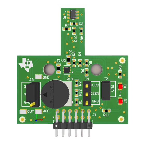
Page 25: Pcb Layout
Schematics, PCB Layout, and Bill of Materials 6.2 PCB Layout Figure 6-2 through Figure 6-5 show the PCB layers of the EVM. Figure 6-2. Top View SBAU376 – DECEMBER 2021 TMAG5328 Evaluation Module Submit Document Feedback Copyright © 2021 Texas Instruments Incorporated... - Page 26 All manuals and user guides at all-guidesbox.com Schematics, PCB Layout, and Bill of Materials www.ti.com Figure 6-3. Top Layer TMAG5328 Evaluation Module SBAU376 – DECEMBER 2021 Submit Document Feedback Copyright © 2021 Texas Instruments Incorporated...
- Page 27 All manuals and user guides at all-guidesbox.com www.ti.com Schematics, PCB Layout, and Bill of Materials Figure 6-4. Bottom View SBAU376 – DECEMBER 2021 TMAG5328 Evaluation Module Submit Document Feedback Copyright © 2021 Texas Instruments Incorporated...
- Page 28 All manuals and user guides at all-guidesbox.com Schematics, PCB Layout, and Bill of Materials www.ti.com Figure 6-5. Bottom Layer TMAG5328 Evaluation Module SBAU376 – DECEMBER 2021 Submit Document Feedback Copyright © 2021 Texas Instruments Incorporated...
-
Page 29: Bill Of Materials
RES, 0, 5%, 0.063 W, 0402 0402 RC0402JR-070RL Yageo America 4.3k RES, 4.3 k, 5%, 0.063 W, AEC- 0402 CRCW04024K30JNED Vishay-Dale Q200 Grade 0, 0402 SBAU376 – DECEMBER 2021 TMAG5328 Evaluation Module Submit Document Feedback Copyright © 2021 Texas Instruments Incorporated... - Page 30 RES, 10.0 k, 1%, 0.063 W, AEC- 0402 RMCF0402FT10K0 Stackpole Electronics Q200 Grade 0, 0402 RES, 91 k, 5%, 0.063 W, AEC- 0402 CRCW040291K0JNED Vishay-Dale Q200 Grade 0, 0402 TMAG5328 Evaluation Module SBAU376 – DECEMBER 2021 Submit Document Feedback Copyright © 2021 Texas Instruments Incorporated...
- Page 31 All manuals and user guides at all-guidesbox.com STANDARD TERMS FOR EVALUATION MODULES Delivery: TI delivers TI evaluation boards, kits, or modules, including any accompanying demonstration software, components, and/or documentation which may be provided together or separately (collectively, an “EVM” or “EVMs”) to the User (“User”) in accordance with the terms set forth herein.
- Page 32 All manuals and user guides at all-guidesbox.com www.ti.com Regulatory Notices: 3.1 United States 3.1.1 Notice applicable to EVMs not FCC-Approved: FCC NOTICE: This kit is designed to allow product developers to evaluate electronic components, circuitry, or software associated with the kit to determine whether to incorporate such items in a finished product and software developers to write software applications for use with the end product.
- Page 33 All manuals and user guides at all-guidesbox.com www.ti.com Concernant les EVMs avec antennes détachables Conformément à la réglementation d'Industrie Canada, le présent émetteur radio peut fonctionner avec une antenne d'un type et d'un gain maximal (ou inférieur) approuvé pour l'émetteur par Industrie Canada. Dans le but de réduire les risques de brouillage radioélectrique à...
- Page 34 All manuals and user guides at all-guidesbox.com www.ti.com EVM Use Restrictions and Warnings: 4.1 EVMS ARE NOT FOR USE IN FUNCTIONAL SAFETY AND/OR SAFETY CRITICAL EVALUATIONS, INCLUDING BUT NOT LIMITED TO EVALUATIONS OF LIFE SUPPORT APPLICATIONS. 4.2 User must read and apply the user guide and other available documentation provided by TI regarding the EVM prior to handling or using the EVM, including without limitation any warning or restriction notices.
- Page 35 Notwithstanding the foregoing, any judgment may be enforced in any United States or foreign court, and TI may seek injunctive relief in any United States or foreign court. Mailing Address: Texas Instruments, Post Office Box 655303, Dallas, Texas 75265 Copyright © 2019, Texas Instruments Incorporated...
- Page 36 TI products. TI’s provision of these resources does not expand or otherwise alter TI’s applicable warranties or warranty disclaimers for TI products. TI objects to and rejects any additional or different terms you may have proposed. IMPORTANT NOTICE Mailing Address: Texas Instruments, Post Office Box 655303, Dallas, Texas 75265 Copyright © 2021, Texas Instruments Incorporated...
Need help?
Do you have a question about the TMAG5328EVM and is the answer not in the manual?
Questions and answers