Table of Contents
Advertisement
Quick Links
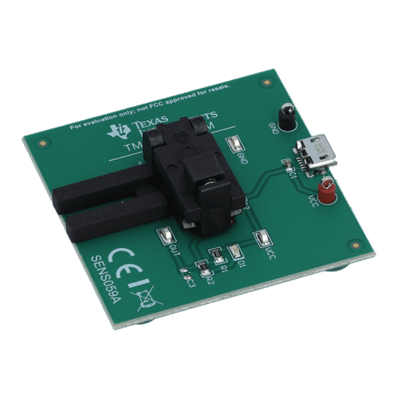
This user's guide describes the characteristics, operation, and use of the TMAG5123 high-precision, in-
plane switch evaluation module (EVM). This EVM is designed to evaluate the performance of the
TMAG5123. This document includes a schematic, printed-circuit board (PCB) layouts, and a complete bill
of materials (BOM).
SLYU056 – June 2020
Submit Documentation Feedback
Copyright © 2020, Texas Instruments Incorporated
User's Guide
SLYU056 – June 2020
TMAG5123EVM
TMAG5123EVM
1
Advertisement
Table of Contents

Related Manuals for Texas Instruments TMAG5123EVM


Summary of Contents for Texas Instruments TMAG5123EVM
- Page 1 (EVM). This EVM is designed to evaluate the performance of the TMAG5123. This document includes a schematic, printed-circuit board (PCB) layouts, and a complete bill of materials (BOM). SLYU056 – June 2020 TMAG5123EVM Submit Documentation Feedback Copyright © 2020, Texas Instruments Incorporated...
-
Page 2: Table Of Contents
Contents ........................Overview ....................TMAG5123EVM Hardware ....................Quick Start Setup and Use ..................... TMAG5123EVM Circuit ................TMAG5123EVM Schematic and PCB Layout ....................... Bill of Materials List of Figures ....................TMAG5123EVM Schematic ....................TMAG5123EVM Top Overlay ....................TMAG5123EVM Top Copper .................. - Page 3 When the magnetic flux density returns to a value below the magnetic release point (B ), the device output returns itself to a high voltage state. The TMAG5123EVM comes prepopulated with a TMAG5123B1 variant for out of the box evaluation. Additional variants can be sampled from www.ti.com.
- Page 4 TMAG5123EVM Hardware www.ti.com Features The layout of the TMAG5123EVM printed-circuit board (PCB) is designed to provide the following features: • Burn-in test socket and precision 3D printed cradle for precise distance evaluation of in-plane sensors • Provides LED feedback to the user to quickly determine output state from the TMAG5123 •...
-
Page 5: Tmag5123Evm Circuit
TMAG5123EVM Circuit www.ti.com TMAG5123EVM Circuit This section summarizes the TMAG5123EVM components. Micro-USB Receptacle J1 is standard micro-USB receptacle. This receptacle provides 5-V power to the board if being used. Test Socket XU1 is a 499-P36-20 Sensata test socket, which is made for devices in a SOT-23 package, such as the TMAG5123. -
Page 6: Tmag5123Evm Schematic And Pcb Layout
TMAG5123EVM Schematic and PCB Layout NOTE: Board layouts are not to scale. These figures are intended to show the board layout. The figures are not intended to be used for manufacturing TMAG5123EVM PCBs. Schematic Figure 1 shows the schematic for the TMAG5123EVM PCB. -
Page 7: Tmag5123Evm Top Overlay
TMAG5123EVM Schematic and PCB Layout www.ti.com PCB Layout Figure 2 through Figure 5 illustrate the PCB layout for the TMAG5123EVM. Figure 2. TMAG5123EVM Top Overlay Figure 3. TMAG5123EVM Top Copper Figure 4. TMAG5123EVM Bottom Copper Figure 5. TMAG5123EVM Bottom Overlay SLYU056 – June 2020... -
Page 8: Bill Of Materials
Bill of Materials www.ti.com Bill of Materials Table 4 provides the parts list for the TMAG5123EVM. Table 4. TMAG5123EVM Bill of Materials DESIGNATOR VALUE DESCRIPTION PACKAGE PART NUMBER MANUFACTURER ALTERNATE PART ALTERNATE REFERENCE NUMBER MANUFACTURER C1, C2 0.1uF CAP, CERM, 0.1 uF, 50 V, +/- 10%, X7R, 0603... - Page 9 TI products. TI’s provision of these resources does not expand or otherwise alter TI’s applicable warranties or warranty disclaimers for TI products. TI objects to and rejects any additional or different terms you may have proposed. IMPORTANT NOTICE Mailing Address: Texas Instruments, Post Office Box 655303, Dallas, Texas 75265 Copyright © 2022, Texas Instruments Incorporated...
Need help?
Do you have a question about the TMAG5123EVM and is the answer not in the manual?
Questions and answers