Table of Contents
Advertisement
Quick Links
www.ti.com
User's Guide
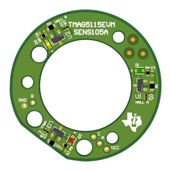
TMAG5115 Evaluation Module
This user's guide describes the characteristics, operation, and use of the TMAG5115 high performance Hall-
effect latch evaluation module (EVM). This EVM is designed to evaluate the performance of the TMAG5115. This
document includes a schematic, printed circuit board (PCB) layouts, and a complete bill of materials (BOM).
1
Overview..................................................................................................................................................................................2
Contents.............................................................................................................................................2
1.2 Related Documentation from Texas Instruments...............................................................................................................
2 TMAG5115EVM Hardware......................................................................................................................................................
3 EVM Operation........................................................................................................................................................................
3.1 Quick Start Setup...............................................................................................................................................................
Operation.......................................................................................................................................................4
4 BLDC Motor Manufacturers.................................................................................................................................................
Circuitry......................................................................................................................................................13
SBAU410 - OCTOBER 2022
Submit Document Feedback
ABSTRACT
Table of Contents
Layout......................................................................................................................14
Copyright © 2022 Texas Instruments Incorporated
Table of Contents
13
TMAG5115 Evaluation Module
2
3
3
3
1
Advertisement
Table of Contents

Subscribe to Our Youtube Channel
Related Manuals for Texas Instruments TMAG5115


Summary of Contents for Texas Instruments TMAG5115
-
Page 1: Table Of Contents
This user’s guide describes the characteristics, operation, and use of the TMAG5115 high performance Hall- effect latch evaluation module (EVM). This EVM is designed to evaluate the performance of the TMAG5115. This document includes a schematic, printed circuit board (PCB) layouts, and a complete bill of materials (BOM). -
Page 2: Overview
Table 1-2 lists the contents of the TMAG5115EVM kit. Contact the Texas Instruments Product Information Center if any components are missing. TI highly recommends checking the TMAG5115 family product folder on the TI website at www.ti.com for further information regarding this product. -
Page 3: Tmag5115Evm Hardware
LED lights turn on and off. An alternative way of evaluating the TMAG5115 is by using the EVM to commutate a brushless direct current (BLDC) motor. The TMAG5115EVM follows a standard form factor for the Hall-effect sensor boards found in various NEMA17 BLDC motors. -
Page 4: Bldc Motor Operation
3-2). The EVM features three functionally independent circuits, one for each of the TMAG5115 devices on the PC board, with each sensor spaced 120° apart. The three sensors and the specific 120° spacing yield what is commonly referred to as a six-step commutation sequence, a common motor commutation algorithm for sensored motor control. - Page 5 EVM Operation Figure 3-3. Six-Step Motor Commutation Control Scheme SBAU410 – OCTOBER 2022 TMAG5115 Evaluation Module Submit Document Feedback Copyright © 2022 Texas Instruments Incorporated...
- Page 6 See Figure 3-4. After the screws are removed, the backplate of the motor should come loose. Figure 3-4. BLDC Motor (Bottom) TMAG5115 Evaluation Module SBAU410 – OCTOBER 2022 Submit Document Feedback Copyright © 2022 Texas Instruments Incorporated...
- Page 7 2. Remove the three screws that currently hold the sensors to the bottom of the housing and remove the board. Figure 3-5. Figure 3-5. Hall Sensor Board Removal SBAU410 – OCTOBER 2022 TMAG5115 Evaluation Module Submit Document Feedback Copyright © 2022 Texas Instruments Incorporated...
- Page 8 Return the screws that were removed in the previous step and tighten. See Figure 3-6 TMAG5115EVM alignment inside the motor. Figure 3-6. TMAG5115EVM on NEMA17 Motor Module TMAG5115 Evaluation Module SBAU410 – OCTOBER 2022 Submit Document Feedback Copyright © 2022 Texas Instruments Incorporated...
- Page 9 Hall-effect sensor inputs. 3.2.3 Example Using MCT8316ZTEVM Texas Instruments offers several motor drivers that can be used to spin BLDC motors. This section explains what connections must be made to spin a motor using the MCT8316ZEVM: 3.2.3.1 MCT8316Z Overview The MCT8316Z is an integrated three-phase gate driver IC with sensored trapezoidal control for motor drive applications.
- Page 10 Guide) to monitor real-time speed of the motor, put the MCT8316ZT into a low-power sleep mode, and read status of the LEDs. Figure 3-8. Reference for MCT8316ZTEVM Quick Start Guide TMAG5115 Evaluation Module SBAU410 – OCTOBER 2022 Submit Document Feedback Copyright © 2022 Texas Instruments Incorporated...
- Page 11 Connect the white wire Hall C to HPC. Figure 3-9 demonstrates the connections mentioned in steps 2-a through 2-e. Figure 3-9. MCT8316ZTEVM Connections SBAU410 – OCTOBER 2022 TMAG5115 Evaluation Module Submit Document Feedback Copyright © 2022 Texas Instruments Incorporated...
- Page 12 For more information on the MCT8316ZTEVM, refer to the MCT8316ZTEVM User's Guide and the MCT8316Z product page. For more information on other TI BLDC motor drivers, go to ti.com/BLDC. TMAG5115 Evaluation Module SBAU410 – OCTOBER 2022 Submit Document Feedback Copyright © 2022 Texas Instruments Incorporated...
-
Page 13: Bldc Motor Manufacturers
This section summarizes the TMAG5115EVM components: R1, R2, and R3 function as pullup resistors for the open-drain output of the TMAG5115. R4, R5, and R6 are current-limiting resistors to control the output intensity of the signal diodes D1, D2, and D3. -
Page 14: Tmag5115Evm Schematic And Pcb Layout
HALLA 1.0uF 0.1uF 0.1uF TMAG5115B1CQDBZR CS63CY2C 2.2k HALLB 1.0uF 0.1uF 0.1uF TMAG5115B1CQDBZR CS63BR 6C 2.2k HALLC 1.0uF 0.1uF 0.1uF TMAG5115B1CQDBZR Figure 6-1. TMAG5115EVM Schematic TMAG5115 Evaluation Module SBAU410 – OCTOBER 2022 Submit Document Feedback Copyright © 2022 Texas Instruments Incorporated... - Page 15 TMAG5115EVM Schematic and PCB Layout 6.2 PCB Layout Figure 6-2. TMAG5115EVM Top Copper Figure 6-3. TMAG5115EVMBottom Copper Figure 6-4. TMAG5115EVM Top Overlay Figure 6-5. TMAG5115EVM Bottom Overlay SBAU410 – OCTOBER 2022 TMAG5115 Evaluation Module Submit Document Feedback Copyright © 2022 Texas Instruments Incorporated...
- Page 16 3051 WH005 Alpha Wire Blue Wire 22AWG, 40cm Blue Wire 3051 BL005 Alpha Wire Red Wire 22AWG, 40cm Red Wire 3051 RD005 Alpha Wire TMAG5115 Evaluation Module SBAU410 – OCTOBER 2022 Submit Document Feedback Copyright © 2022 Texas Instruments Incorporated...
- Page 17 STANDARD TERMS FOR EVALUATION MODULES Delivery: TI delivers TI evaluation boards, kits, or modules, including any accompanying demonstration software, components, and/or documentation which may be provided together or separately (collectively, an “EVM” or “EVMs”) to the User (“User”) in accordance with the terms set forth herein.
- Page 18 www.ti.com Regulatory Notices: 3.1 United States 3.1.1 Notice applicable to EVMs not FCC-Approved: FCC NOTICE: This kit is designed to allow product developers to evaluate electronic components, circuitry, or software associated with the kit to determine whether to incorporate such items in a finished product and software developers to write software applications for use with the end product.
- Page 19 www.ti.com Concernant les EVMs avec antennes détachables Conformément à la réglementation d'Industrie Canada, le présent émetteur radio peut fonctionner avec une antenne d'un type et d'un gain maximal (ou inférieur) approuvé pour l'émetteur par Industrie Canada. Dans le but de réduire les risques de brouillage radioélectrique à...
- Page 20 www.ti.com EVM Use Restrictions and Warnings: 4.1 EVMS ARE NOT FOR USE IN FUNCTIONAL SAFETY AND/OR SAFETY CRITICAL EVALUATIONS, INCLUDING BUT NOT LIMITED TO EVALUATIONS OF LIFE SUPPORT APPLICATIONS. 4.2 User must read and apply the user guide and other available documentation provided by TI regarding the EVM prior to handling or using the EVM, including without limitation any warning or restriction notices.
- Page 21 Notwithstanding the foregoing, any judgment may be enforced in any United States or foreign court, and TI may seek injunctive relief in any United States or foreign court. Mailing Address: Texas Instruments, Post Office Box 655303, Dallas, Texas 75265 Copyright © 2019, Texas Instruments Incorporated...
- Page 22 TI products. TI’s provision of these resources does not expand or otherwise alter TI’s applicable warranties or warranty disclaimers for TI products. TI objects to and rejects any additional or different terms you may have proposed. IMPORTANT NOTICE Mailing Address: Texas Instruments, Post Office Box 655303, Dallas, Texas 75265 Copyright © 2022, Texas Instruments Incorporated...
Need help?
Do you have a question about the TMAG5115 and is the answer not in the manual?
Questions and answers