Table of Contents
Advertisement
Quick Links
Advertisement
Table of Contents

Related Manuals for Ross openGear GPI-100


Summary of Contents for Ross openGear GPI-100
- Page 1 GPI-100 VANC to GPIO Trigger Inserter/Decoder User Manual...
- Page 2 The material in this manual is furnished for informational use only. It is subject to change without notice and should not be construed as commitment by Ross Video Limited. Ross Video Limited assumes no responsibility or liability for errors or inaccuracies that may appear in this manual.
- Page 3 Important Regulatory and Safety Notices to Service Personnel Before using this product and nay associated equipment, refer to the “Important Safety Instructions” listed below to avoid personnel injury and to prevent product damage. Product may require specific equipment, and/or installation procedures to be carried out to satisfy certain regulatory compliance requirements.
- Page 4 Notice — Changes or modifications to this equipment not expressly approved by Ross Video Limited could void the user’s authority to operate this equipment. CANADA This Class “A”...
- Page 5 The crossed out wheelie bin symbol invites you to use these systems. If you need more information on the collection, re-use, and recycling systems, please contact your local or regional waste administration. You can also contact Ross Video for more information on the environmental performance of our products.
- Page 6 Company Address Ross Video Limited Ross Video Incorporated 8 John Street P.O. Box 880 Iroquois, Ontario, K0E 1K0 Ogdensburg, New York Canada USA 13669-0880 General Business Office: (+1) 613 • 652 • 4886 Fax: (+1) 613 • 652 • 4425 Technical Support: (+1) 613 •...
-
Page 7: Table Of Contents
Contents Introduction Overview..........................1-2 Features........................1-2 Functional Block Diagram....................1-3 User Interfaces ........................1-4 DashBoard Control System™ ................1-4 On-screen Menu System..................1-4 Documentation Terms and Conventions................1-5 Installation Before You Begin ........................ 2-2 Static Discharge..................... 2-2 Unpacking......................2-2 Quick Start ........................... 2-3 Installing the GPI-100...................... - Page 8 Service Information Troubleshooting Checklist ....................7-2 Reset Button......................7-2 Warranty and Repair Policy ....................7-3 ii • Contents GPI-100 User Manual (Iss. 03)
-
Page 9: Introduction
Congratulations on choosing an openGear GPI-100 VANC to GPIO Trigger Inserter/Decoder. Your GPI-100 is part of a full line of Digital Products within the openGear Terminal Equipment family of products, backed by Ross Video’s experience in engineering and design expertise since 1974. -
Page 10: Overview
Overview The GPI-100 enables GPIO triggers to be carried in the Vertical Ancillary (VANC) data area of an SDI (SMPTE 259) or HD-SDI (SMPTE 292) video signal, in accordance with SMPTE 291 and other related standards. The GPI-100, as an encoder, reads GPIO inputs and inserts them into the VANC. -
Page 11: Functional Block Diagram
Functional Block Diagram This section provides the functional block diagram that outlines the workflow of the GPI-100. HD/SD-SDI IN BYPASS HD/SD-SDI OUT EQUALIZE/ INSERT SERIALIZE DESERIALIZE VANC HD/SD-SDI MON OUT EXTRACT VANC GPIOs SERIALIZE OSD/SD-SDI OUT Figure 1.1 Simplified Block Diagram GPI-100 User Manual (Iss. -
Page 12: User Interfaces
User Interfaces The GPI-100 includes two user interfaces. DashBoard Control System™ The DashBoard Control System™ enables you to monitor and control openGear frames and cards from a computer. DashBoard communicates with other cards in the DFR-8300 series frame through the Network Controller Card. The DashBoard Control System software and manual are available for download from our website. -
Page 13: Documentation Terms And Conventions
Documentation Terms and Conventions The following terms and conventions are used throughout this manual: • “Board” and “Card” refer to the GPI-100 card itself, including all components and switches. • “DashBoard” refers to the DashBoard Control System™. • “Frame” refers to the DFR-8300 series frame that houses the GPI-100 card. •... - Page 14 1–6 • Introduction GPI-100 User Manual (Iss. 03)
-
Page 15: Installation
Installation In This Chapter This chapter provides instructions for installing the GPI-100, installing the card into the frame, cabling details, and updating the card software. The following topics are discussed: • Before You Begin • Quick Start • Installing the GPI-100 •... -
Page 16: Before You Begin
Unpacking Unpack each GPI-100 you received from the shipping container and ensure that all items are included. If any items are missing or damaged, contact your sales representative or Ross Video directly. 2–2 • Installation... -
Page 17: Quick Start
2. Install DashBoard on a computer connected to the LAN. The DashBoard Control System™ software and user manual are available from the Ross Video website. 3. Install each rear module in the frame, as described in the section “Installing a Rear Module”... - Page 18 • Click Accept to apply your changes. 6. Select the Log tab of the decode card. Each time your GPIO source sends a trigger it appears in the log. This tab shows the last 20 entries of the log file maintained on the GPI-100.
-
Page 19: Installing The Gpi-100
Installing the GPI-100 This section outlines how to install a rear module and card in a DFR-8300 series frame. Refer to the section “Cabling for the GPI-100” on page 2-7 for cabling details. Rear Modules When installing the GPI-100: • DFR-8310 series frames —... -
Page 20: Installing The Gpi-100
Installing the GPI-100 Use the following procedure to install the GPI-100 in a DFR-8300 series frame: 1. Locate the Rear Module you installed in the procedure “Installing a Rear Module” on page 2-5. Notice — Heat and power distribution requirements within a frame may dictate specific slot placements of cards. -
Page 21: Cabling For The Gpi-100
Cabling for the GPI-100 This section provides information for connecting cables to the installed Rear Modules on the DFR-8300 series frames. Connect the input and output cables according to the following sections. Rear Module Cabling This section provides cabling diagrams for the rear modules. The type of rear module depends on the frame the card is installed in. - Page 22 SDI Out — BNC 3 BNC 3 carries the main program output from the GPI-100, consisting of the signal applied to BNC 1, with VANC data packets inserted. BNC 1 is routed directly to BNC 3 (without passing through the GPI-100), under the following circumstances: power off, GPI-100 card removed, GPI-100 Bypass push-button out, software selection or certain major error conditions.
-
Page 23: Software Upgrades
DashBoard Control System™. Use the following procedure to upgrade the software on a GPI-100: 1. Contact Ross Technical Support for the latest software version file. 2. Launch the DashBoard client on your computer. 3. Display a tab for the card you wish to upgrade by double-clicking its status indicator in the Basic Tree View. - Page 24 2–10 • Installation GPI-100 User Manual (Iss. 03)
-
Page 25: User Controls
User Controls In This Chapter This chapter provides a general overview of the user controls available on the GPI-100. The following topics are discussed: • Card Overview • Control and Monitoring Features GPI-100 User Manual (Iss. 03) User Controls • 3–1... -
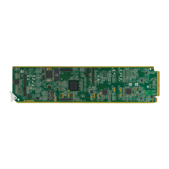
Page 26: Card Overview
Card Overview This section provides a general overview of the GPI-100 card components. Figure 3.1 GPI-100 — Components 1) Bypass Switch (SW1) 2) Menu Switch (SW2) 3) Reset Switch (SW3) 1. Bypass Switch (SW1) If the GPI-100 is installed in the MDL-R20 rear module, this two-position push-button can be used to control the relay. -
Page 27: Control And Monitoring Features
Control and Monitoring Features This section provides information on the card-edge LEDs for the GPI-100. Refer to Figure 3.2 for the location of the LEDs. POWER LED (DS1) BYPASS LED (DS2) Bypass Switch (SW1) PGM VIDEO IN LED (DS3) PGM VIDEO OUT LED (DS4) DS5 LED DS6 LED Menu Switch (SW2) - Page 28 Table 3.1 LEDs on the GPI-100 Color Display and Description When lit green, the Program Video output serializer is locked to Green PGM VID a valid input. OUT (DS4) When lit red, there is a hardware fault on the card. This LED is not implemented.
-
Page 29: Configuration
Configuration In This Chapter This chapter explains how to use the user interface to set up the GPI-100. This discussion is based on the use of DashBoard through a network connection. The order of sections in this chapter follows the workflow required to set up the GPI-100 for operation. It is recommended that you proceed through the following sections in order to achieve the best possible understanding of the product. -
Page 30: General Settings
General Settings This section provides a summary of the initial tasks you may wish to perform before configuring your card for monitoring VANC data. Before proceeding to any of the other sections, please ensure that these settings are correct, as they will have an effect on the operation of the other functions. -
Page 31: Configuring Gpios
Configuring GPIOs The GPI-100 has eight GPIOs connections on the rear module. The GPIO Mask tab controls which of the eight are active. The GPI-100 will only generate triggers for enabled GPIOs in encode mode and will ignore changes in the GPIO state of unchecked GPIOs. While decoding triggers from the VANC, the GPI-100 will only drive GPIOs that are enabled. -
Page 32: Setting The Logging Timestamp
Setting the Logging Timestamp The GPI-100 logs any changes of the GPIO state for both the encode and decode cards. For the timestamp to be valid, you must have the time set on the GPI-100. There are three possible methods for setting the time; network time server, timecode or manually. To set the logging timestamp 1. -
Page 33: Downloading Log Files
Downloading Log Files The Log tab shows the last 20 trigger events. An event occurs any time there is a change to any of the GPIOs that are currently enabled. It is logged when a GPIO goes high and also logged when it returns to low. -
Page 34: Monitoring
Product Status The Product tab provides read-only information, such as board revision, serial number, and rear module type. This information is helpful to a Ross Video technical support when there are questions about the operation of the unit. GPIO Status Tab The GPIO Status tab reports the status of the eight GPIO inputs/outputs. -
Page 35: Using The On-Screen Menus
Using the On-Screen Menus In This Chapter This chapter explains how to use the Menu switch (SW3) functions available on the On-screen Display (OSD) of the GPI-100. It does not describe each available menu; for information on these, refer to the chapter “Configuration” on page 4-1. The purpose of this chapter is to explain how to navigate the menus and access the available functions and settings. -
Page 36: On-Screen Display Overview
On-screen Display Overview This section briefly describes how to access and navigate through the menus in the on-screen display (OSD). The OSD feature is displayed on a separate composite monitoring output. When activated, the card status and parameters can be viewed and adjusted using the card-mounted menu switch and an easy to use menu system. -
Page 37: Osd Layout And Navigation
OSD Layout and Navigation A menu, similar shown below, is displayed on the OSD output. GPI-100 GPIO VANC Encoder Product Settings EXIT Product GPI-310 Manufacturer Hardware Rev Software Rev Firmware Rev Rear Module Current (mA) Serial Number Current Time 20:37:12 Current Date 2011/06/02 Slot 6... -
Page 38: Using The Menus
Using the Menus The available menus that can be selected via the OSD are described in Table 5.1. Table 5.1 Available Menus Status (left column) Setup Menus (center column) Exit (right) Product Settings Exit GPIO Status Time GPIO Mask The use of the menus to change settings will be illustrated by the following example: 1. -
Page 39: Specifications
Specifications In This Chapter This chapter provides the technical specification information for the GPI-100. Note that technical specifications are subject to change without notice. The following topics are discussed: • Technical Specifications GPI-100 User Manual (Iss. 03) Specifications • 6–1... -
Page 40: Technical Specifications
Technical Specifications This section provides technical specifications for the GPI-100. Table 6.1 GPI-100 Technical Specifications Category Parameter Specification Number of Inputs 1 Program input 480i 59.94 (SMPTE 259M) 576i 50 (SMPTE 259M) 1080i 50, 59.94, 60 (SMPTE 292M) Data Rates and SMPTE Standards Accommodated 720p 50, 59.94, 60 (SMPTE 292M) 1080p 23.98, 24 (SMPTE 292M) - Page 41 Service Information In This Chapter This chapter contains the following sections: • Troubleshooting Checklist • Warranty and Repair Policy GPI-100 User Manual (Iss. 03) Service Information • 7–1...
- Page 42 Reset Button In the unlikely event of a complete card failure, you may be instructed by a Ross Technical Support specialist to perform a complete software reload on the GPI-100.
- Page 43 FIVE (5) years from the date of shipment from our factory. In the event that your GPI-100 proves to be defective in any way during this warranty period, Ross Video Limited reserves the right to repair or replace this piece of equipment with a unit of equal or superior performance characteristics.
- Page 44 Contact Us Contact our friendly and professional support representatives for the following: • Name and address of your local dealer • Product information and pricing • Technical support • Upcoming trade show information Telephone: +1 613 • 652 • 4886 Technical After Hours Emergency: +1 613 •...
Need help?
Do you have a question about the openGear GPI-100 and is the answer not in the manual?
Questions and answers