Table of Contents
Advertisement
Quick Links
Advertisement
Table of Contents
Troubleshooting

Related Manuals for Ross Opengear UDC-8625A Series


Summary of Contents for Ross Opengear UDC-8625A Series
- Page 1 UDC-8625A Series 3G/HD/SD SDI Multi-Function Format Converters User Manual...
- Page 2 Ross has become well known for the Ross Video Code of Ethics. It guides our interactions and empowers our employees. I hope you enjoy reading it below. If anything at all with your Ross experience does not live up to your expectations be sure to reach out to us at solutions@rossvideo.com.
- Page 3 Ross Video. While every precaution has been taken in the preparation of this document, Ross Video assumes no responsibility for errors or omissions. Neither is any liability assumed for damages resulting from the use of the information contained herein.
- Page 4 Operation of this equipment in a residential area is likely to cause harmful interference in which case the user will be required to correct the interference at his own expense. Notice — Changes or modifications to this equipment not expressly approved by Ross Video Ltd. could void the user’s authority to operate this equipment. Canada This Class “A”...
- Page 5 To avoid the potential release of those substances into the environment and to diminish the need for the extraction of natural resources, Ross Video encourages you to use the appropriate take-back systems. These systems will reuse or recycle most of the materials from your end-of-life equipment in an environmentally friendly and health conscious manner.
-
Page 7: Table Of Contents
Contents Introduction Product Overview ........................ 1-2 Features ..........................1-3 Functional Block Diagrams ....................1-4 UDC-8625A Block Diagram................. 1-4 Format Conversion ......................1-6 Supported Format Conversions ................1-6 Output Format Reference Compatibility ................1-7 User Interfaces ........................1-8 DashBoard ......................1-8 Card-edge Controls.................... - Page 8 Configuring the Input Signal Timing Display ..............3-10 Configuring the Loss of Input Behavior ................3-11 Specifying the Output during a Loss of Input ............. 3-11 Previewing the Loss of Input Setting..............3-12 Configuring the Edit Permissions ..................3-13 Software Upgrades ......................3-14 Loading the Factory Defaults.....................
- Page 9 Loading a Media File..................... 7-5 Operation External Key and Internal Key Features................8-2 Key 1 Wings Setup ......................8-3 Key 2 Setup.......................... 8-4 Configuring Key 2....................8-4 Masking a Key....................... 8-5 Logo Setup ........................... 8-6 Adjusting the Proc Amp Controls..................8-7 Performing Transitions ......................
- Page 10 4:3 SD to HD (Zoom) ......................11-3 4:3 SD to 16:9 SD (Pillarbox) .................... 11-4 HD to 4:3 SD (Letterbox) ....................11-5 HD to 4:3 SD (Zoom) ......................11-6 Appendix D. Cascade Feature Cabling for the Cascade Feature ..................12-2 Cabling Overview ....................
-
Page 11: Introduction
A Word of Thanks Congratulations on choosing an openGear UDC-8625A(-A/-B) 3G/HD/SD SDI Multi-Function Format Converter. Thank you for joining the group of worldwide satisfied Ross Video customers! Should you have a question pertaining to the installation or operation of your card, please contact us at the numbers listed on the back cover of this manual. -
Page 12: Product Overview
Product Overview The UDC-8625A series are feature rich 3G / HD / SD SDI converters that support all traditional formats including 1080p, 1080i, 720p, 480i, and 576i. Audio and video synchronization is combined with a signal processor, offering full control of the 16 channels of audio, with gain, invert, shuffle and sample rate conversion. -
Page 13: Features
Features The following features are standard on the UDC-8625A series cards: • Compliance with SMPTE 259M, SMPTE 292M, SMPTE 424M, SMPTE 272M-A 48kHz 24bit, and SMPTE 299M-2004 48kHz 24bit • Passes SMPTE 291M formatted vertical ancillary data from input to output •... -
Page 14: Functional Block Diagrams
Functional Block Diagrams This section provides functional block diagrams that outline the workflow of the UDC-8625A series. Note that the number of AES inputs and outputs is determined using the AES IO Config menu in DashBoard. UDC-8625A Block Diagram Figure 1.1 outlines the workflow of the UDC-8625A. EMBEDDED AUDIO EMBEDDED AUDIO... - Page 15 UDC-8625A-A and UDC-8625A-B Block Diagram Figure 1.2 outlines the workflow of the UDC-8625A-A when using the 8320AR-053A Rear Module. When using the 8320AR-053B Rear Module, HD-BNC connectors are available. When using the UDC-8625A-B, the 8320AR-052A Rear Module provides WECO™ connectors. AES AUDIO* AES AUDIO* AES SOURCE...
-
Page 16: Format Conversion
Format Conversion The UDC-8625A series provides up-conversion, down-conversion, and cross-conversion. The card converts the incoming video to any supported video format and incorporates a video frame synchronizer to allow the output video to be timed to an external video reference. The UDC-8625A series can cleanly switch between SDI IN 1 and SDI IN 2 for conversion. -
Page 17: Output Format Reference Compatibility
Output Format Reference Compatibility The UDC-8625A series locks the output video to an external reference. Reference compatibility is shown in Table 1.2. A check-mark indicates a supported output reference compatibility. Table 1.2 Output/Reference Compatibility Output Reference 480i 59.94Hz 720p 59.94Hz 1080i 59.94Hz 1080p 59.94Hz 576i 50Hz 720p 50Hz 1080i 50Hz 1080p 50Hz ... -
Page 18: User Interfaces
DashBoard software and manual are available for download from our website Note — Ross Video recommends using the MFC-8320-N or MFC-OG3-N Network Controller Card for optimal performance especially when multiple UDC-8625A series cards are installed in one frame. An MFC-8320-S or MFC-8322-S Controller Card can be used, but you may encounter delays in updating settings in DashBoard and upgrading the card software. -
Page 19: Documentation Terms And Conventions
Documentation Terms and Conventions The following terms and conventions are used throughout this manual. Terms The following terms are used: • “Active image” refers to the portion of the video picture area (production aperture) that is being utilized for output content. Active image excludes letterbox bars and pillarbox bars. •... - Page 20 1–10 • Introduction UDC-8625A Series User Manual (Iss. 11)
-
Page 21: Installation
Installation In This Chapter This chapter provides instructions for the basic physical installation of your UDC-8625A series card. The following topics are discussed: • Before You Begin • Card Overview • Card Installation • UDC-8625A Cabling • UDC-8625A-A Cabling • UDC-8625A-B Cabling •... -
Page 22: Before You Begin
Unpacking Unpack each card you received from the shipping container and ensure that all items are included. If any items are missing or damaged, contact your sales representative or Ross Video directly. 2–2 • Installation UDC-8625A Series User Manual (Iss. 11) -
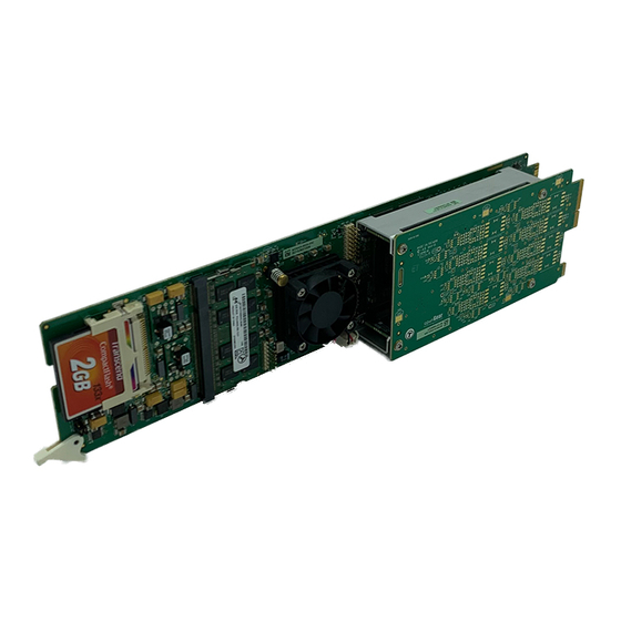
Page 23: Card Overview
Pressing this button resets the microprocessor and re-initializes the card. This is a hard reset of the card and unsaved settings are not retained. This may cause loss of data and should only be performed as advised by Ross Video Technical Support. 3. JP5, JP6 These jumpers are not yet implemented and must be left in the default position of Pin 2 (center) and Pin 3 (bottom). -
Page 24: Card-Edge Leds
Card-edge LEDs This section describes the card-edge LEDs. Refer to Figure 2.3 for LED locations. Note that the Audio Daughter Card is only available on the UDC-8625A-A and UDC-8625A-B. ERROR/OK LED (DS1) SDI IN 1 LED (DS2) SDI IN 2 LED (DS3) SDI IN 3 LED (DS4) SDI IN 4 LED (DS5) REF STAT LED (DS6) -
Page 25: Card Installation
Card Installation This section provides a brief overview of the physical installation of the UDC-8625A series cards. The procedure for installing a rear module and card is the same regardless of the rear module and frame used. However, the rear module you install depends on the frame and the features you require. -
Page 26: Installing The Card
UDC-8625A-B Rear Module When installing the UDC-8625A-B in the DFR-8321 series frame or the OG3-FR series frames, the following rear module is supported: • 8320AR-052A — This rear module provides one analog reference input, four SDI inputs, four SDI outputs, four GPIOs, eight AES/EBU WECO™ connections, a serial port, and an ethernet port. - Page 27 To install the card in an openGear frame 1. When using the 8320AR-041 or 8322AR-065 rear module, install the card in an even numbered slot (e.g. slot 2, 4, 6 etc.). Note — The slot number is dependent on the slot combinations you installed the rear module in.
-
Page 28: Udc-8625A Cabling
UDC-8625A Cabling This section provides an overview of the UDC-8625A cabling. 8310AR-033 Rear Module Figure 2.5 outlines the cabling designations when using the 8310AR-033 rear module. This rear module occupies four slots in the frame and accommodates one card. GPIO 3 GPIO 1 SDI IN 1 GPIO 2... - Page 29 8320AR-041 Rear Module Figure 2.6 outlines the cabling designations when using the 8320AR-041 rear module. This rear module occupies two slots in the frame and accommodates one card. SDI IN 3 SDI IN 2 SDI IN 1 SDI IN 4 SDI OUT 1 SDI OUT 2 SDI OUT 3...
- Page 30 8320AR-055 Rear Module Figure 2.8 outlines the cabling designations when using the 8320AR-055 rear module. This rear module occupies four slots in the frame and accommodates one card. SDI IN 1 SDI IN 2 SDI IN 3 SDI IN 4 SDI OUT 1 SDI OUT 2 GPIO 6...
-
Page 31: Udc-8625A-A Cabling
UDC-8625A-A Cabling Note that when the card is configured as 4 in and 4 out, the AES 1-4 connections are the inputs and the AES 5-8 connections are the outputs. Each rear module occupies four slots in the frame and accommodates one card. 8320AR-053A Cabling Figure 2.10 outlines the cabling designations when using the 8320AR-053A rear module. -
Page 32: Udc-8625A-B Cabling
UDC-8625A-B Cabling Refer to Figure 2.12 and the rear module label, for cabling designations. Note that when the card is configured as 4 in and 4 out, the AES 1-4 connections are the inputs and the AES 5-8 connections are the outputs. Each rear module occupies four slots in the frame and accommodates one card. -
Page 33: Video Cabling Overview
Video Cabling Overview This section provide information on cabling the video inputs, video outputs, and reference signal for your card. For More Information on... • equalization specifications when using Belden 1694A or equivalent coaxial cable for SDI connections, refer to “Appendix B. Specifications” on page 10-1. Power Fail Relay (8310AR-033, 8320AR-033, and 8320AR-055) There is a power fail relay from the SDI IN 1 to SDI OUT 1 on the 8310AR-033, 8320AR-033, and 8320AR-055 rear modules only. -
Page 34: Cabling A Reference Source
When the Auto Change Over feature is disabled, either SDI IN 1 or SDI IN 2 can be used as a format conversion source, and the user can cleanly transition between them. 2. When using the 8310AR-033, 8320AR-033, or the 8320AR-055 rear modules, the Bypass Relay source will be routed to SDI OUT 1 if the card is unavailable. -
Page 35: Audio Cabling Overview
Audio Cabling Overview This section provides audio cabling information for the UDC-8625A-A and UDC-8625A-B. UDC-8625A-A Cabling Both the 8320AR-053A and 8320AR-053B rear modules each provide eight unbalanced connections for AES sources. Depending on the rear module type, you will have DIN connections (8320AR-053A) or HD-BNC connections (8320AR-053B). -
Page 36: Ethernet Port Cabling
Auto-MDIX ethernet PHY that will switch from straight to crossover automatically as needed. Ross Video does not supply this cable. Refer to Figure 2.14 for a cabling example using the 8320AR-033 rear module installed in an OG3-FR series frame. -
Page 37: Gpio Cabling
GPIO Cabling The UDC-8625A series provides up to eight General Purpose Input (GPI) and Tally pins to interface with external equipment. The number of GPI/Tallies available depends on the rear module type and the card model you are using. Note —The 8320AR-041 rear module does not include GPIO ports. - Page 38 8320AR-033 Rear Module The 8320AR-033 rear module provides eight GPI and Tally pins to interface with external equipment. (Figure 2.16) GPIO 2 GPIO 1 GPIO 4 GPIO 3 GPIO 6 GPIO 5 GPIO 7 GPIO 8 Figure 2.16 8320AR-033 GPIO Connections 8320AR-052 Rear Module The 8320AR-052 rear module provides eight GPI and Tally pins to interface with external equipment.
- Page 39 8320AR-053A and 8320AR-053B Rear Modules The 8320AR-053A and 8320AR-053B rear modules each provide four GPI and Tally pins to interface with external equipment. (Figure 2.19) GPIO 4 GPIO 3 GPIO 2 GPIO 1 Figure 2.19 8320AR-053A and 8320AR-053B GPIO Connections 8320AR-055 Rear Module The 8320AR-055 rear module provides eight GPI and Tally pins to interface with external equipment.
- Page 40 2–20 • Installation UDC-8625A Series User Manual (Iss. 11)
-
Page 41: Configuration
• Using DataSafe Note — Before proceeding, ensure that you are running DashBoard software version 6.2.0 or higher. You can download the DashBoard software and manual from the Ross Video website. UDC-8625A Series User Manual (Iss. 11) Configuration • 3–1... -
Page 42: Using Dashboard
Using DashBoard Before proceeding, ensure that the DashBoard is installed on a PC connected to your facility network. The DashBoard software and user manual are available from the Ross Video website. For More Information on... • using DashBoard, refer to the DashBoard User Manual. -
Page 43: Ethernet Communication Setup
Ethernet Communication Setup If your rear module includes an Ethernet port, you can use it to connect to an ethernet network for communications, software upgrades using DashBoard, media file management via an FTP client, and for viewing thumbnails. To use the rear module Ethernet port, the card must be configured with valid ethernet settings. -
Page 44: Selecting The Reference Source
Selecting the Reference Source The openGear frames support a distributed frame reference, allowing incoming reference signals to feed timing information to all cards in that frame. Thus, a single composite or tri-level sync signal can be used for multiple UDC-8625A series cards. Alternatively, each card accepts a reference signal on the rear module to provide additional system timing flexibility. -
Page 45: Configuring The Video Outputs
Configuring the Video Outputs The Output Setup menus in the Config tab enable you to specify the format for all the card outputs, configure what to output, and adjust the timing of all outputs. Note — The Wings, Key Video, and Key Alpha sources must be the same format as the output format. - Page 46 • Test Pattern — Select this option to assign a test pattern to the selected output. You can specify a test pattern to use by selecting an option from the Test Pattern menu. • External Wings — Select this option to output a copy of the Key 1 - Wings source (input 1, 2, 3, or 4).
-
Page 47: Setting Up Gpi/Tally Communications
Setting up GPI/Tally Communications This section explains how to configure communications for GPIs and Tallies on the card using the menus and options available in DashBoard. Each of the GPI/O ports can be configured as a GPI or Tally output. GPI Overview When configured as a GPI, a port behaves as an input, and can be used to trigger actions such as Cut/Dissolve the Key and/or Background. -
Page 48: To Set Up Gpi/Tally Communications
To set up GPI/Tally communications Note — The 8320AR-041 rear module does not include GPI/O ports. You can still configure the settings in the GPI/Tally tab, but your changes will not take effect. 1. From the Device View in DashBoard, select the Config tab. 2. -
Page 49: Configuring The Transition Buttons
Configuring the Transition Buttons The Transition Behavior option enables you to specify how the Cut and Auto buttons, located in the On Air Control tab, behave when toggled during a transition. For More Information on... • the behavior options, refer to Table 9.9 on page 9-11. To configure the transition buttons 1. -
Page 50: Configuring The Input Signal Timing Display
Configuring the Input Signal Timing Display The Timing Display feature enables you to configure how the input signal timing is reported by DashBoard. This information is displayed in the individual Input Timing fields of the Signal tab. The timing display reports the delay of the input signals in output format clocks and lines. To configure the input signal timing for your card 1. -
Page 51: Configuring The Loss Of Input Behavior
Configuring the Loss of Input Behavior You can specify what the card outputs should a loss of input signal occur, or during a change of input format. Specifying the Output during a Loss of Input Use the Loss Of Input setting to specify what the card outputs until the input signal is stable or returns. -
Page 52: Previewing The Loss Of Input Setting
Previewing the Loss of Input Setting Toggle the Loss Of Input button the On Air Control interface to preview what the card outputs during a loss of input signal. The button is lit red, the label changes to , and Preview: ON AIR the Background displays the selection made in the Config >... -
Page 53: Configuring The Edit Permissions
Configuring the Edit Permissions The Personality tab in DashBoard enables you to lock the card permissions so that parameters are read-only and cannot be changed. To configure the card edit permissions 1. From the Device View, select the Config tab. 2. -
Page 54: Software Upgrades
Refer to the section “Ethernet Port Cabling” on page 2-16 for setup details. To upgrade the software on a card 1. Contact Ross Technical Support for the latest software version file. 2. If you are upgrading via the Ethernet port on the rear module: •... - Page 55 • The Reboot Confirm dialog displays, indicating the number of cards that will re-boot. Click Yes to continue the upgrade process. Note that clicking Cancel or No returns you to the Uploading to Selected Devices dialog without rebooting the card(s). •...
-
Page 56: Loading The Factory Defaults
Loading the Factory Defaults If required, the card menu parameters can be reset to the factory default values using the option available in the Load/Save tab. Note — Ethernet settings, reference selection, and the output formats are not reset using this method. To reset the card to the factory default configuration in DashBoard 1. -
Page 57: Using Datasafe
Using DataSafe DataSafe enables you to load and store card parameters automatically, or you can load from and store to a single file in DashBoard. Ensure that you are loading parameters to the same model of card. The DataSafe feature is available for openGear frames using the MFC-8320-N or MFC-OG3-N cards only. - Page 58 3–18 • Configuration UDC-8625A Series User Manual (Iss. 11)
-
Page 59: Afd
AFD and ARC Status Note — Before proceeding, ensure that you are running DashBoard software version 6.2.0 or higher. You can download the DashBoard Control System software and manual from the Ross Video website. UDC-8625A Series User Manual (Iss. 11) AFD • 4–1... -
Page 60: Overview
Overview The UDC-8625A series card uses the input and output AFD settings to configure the Aspect Ratio Converter (ARC). The UDC-8625A series card uses the AFD to: • determine where in the coded frame the active content is, • define the protected area of the active content, and •... - Page 61 Figure 4.2 provides an illustrative example of how an image in a 16:9 coded frame is defined by the applicable AFD Codes. AFD Code:0100 AFD Code:1000, 0010 AFD Code:1001 AFD Code:1010 16:9 Letterbox with aspect 16:9 Coded Full Frame 4:3 Pillarbox 16:9 Full Frame ratio greater than 16:9 with Protected Area...
-
Page 62: Selecting An Arc Mode
Selecting an ARC Mode This section provides information to help you select an ARC mode for your UDC-8625A series card. Auto Output ARC Mode - Auto AFD When the card is configured for Auto Output ARC mode - Auto AFD, the output AFD is based on the input AFD Code. -
Page 63: Using The Force Afd Option
Using the Force AFD Option You must configure the Input Settings when the input AFD is absent or you have chosen the Force AFD option for the ARC Mode: Table 4.3 Input ARC Mode is Output ARC Mode is Result Card ignores any AFD data on the input and applies the settings specified in the AFD Code menu in the Input Settings column. -
Page 64: Blank Number Of Active Lines
Blank Number of Active Lines You can choose to remove encoded signals, like closed caption data and timecode, that may appear at the top of the active video in SD inputs. This only applies to SD inputs with AFD 1000. The remaining lines are processed through the scaler to fill the production aperture, except for SD to SD with no ARC. -
Page 65: Managing The Profiles For Arc
Managing the Profiles for ARC The Aspect Ratio Conversion (ARC) is configured by creating profiles for recalling the AFD settings using the options in the ARC tab in DashBoard. Configuring a Profile A profile specifies the ARC mode, the AFD Code, and aspect ratio for input and output of the card. - Page 66 • For input 16:9 formats — specify where the active picture is displayed by selecting one of the options from the 16:9 AFD Code menu located in the Input Settings column. 6. If you selected Force AFD option for the output settings: •...
-
Page 67: Recalling A Profile
Recalling a Profile You can recall a profile via a button on the Status sub-tab located on the ARC tab, or via GPI. ARC profile recalls are performed within 1 frame. For More Information on... • configuring a GPI, refer to the section “Setting up GPI/Tally Communications” on page 3-7. -
Page 68: Afd And Arc Status
AFD and ARC Status The following fields and tabs provide status information on the ARC and/or AFD: • Video Processing Input — This field in the Signal tab indicates the status of the input. Information such as the format, aspect ratio, coded frame, and the detected AFD code (four digit AFD code and whether AFD is enabled) is also displayed. -
Page 69: Ancillary Data
Ancillary Data In This Chapter Ancillary Data (ANC) is the non-video data that can be embedded within the SDI signal, such as audio, audio metadata, timecode, closed caption data, AFD, and payload identification. This chapter provides an overview of ANC processing for the UDC-8625A series card. The following topics are discussed: •... -
Page 70: Overview
Overview There are two areas in which ancillary data may be found: • HANC — ANC packets that are found in the horizontal blanking region. • VANC — ANC packets that are found in the vertical blanking region. This section outlines how to view incoming status in the Input Status and Input Status:Audio tabs and configure the UDC-8625A series card to manage HANC and VANC data using the options in the ANC tab of DashBoard. -
Page 71: Hanc Pass Through Or Vanc Pass Through
HANC Pass Through or VANC Pass Through The HANC Pass Through and VANC Pass Through settings only apply when the output and the input have the same format. If the input is not synchronous to the output, entire frames of data are duplicated or dropped as part of the frame sync behavior. -
Page 72: Specific Anc Processing
Specific ANC Processing The remainder of the ANC tab controls how ancillary data is inserted in the output when HANC and/or VANC pass through is not enabled. ANC Processing Overview For each packet type the user can control the insertion position. To configure the processing of specific ANC types 1. -
Page 73: Op-42 Processing
• Line # — The card searches only the specified line in the input signal for the VI. 4. Use the Output Line Number menu to specify which line in the output to insert the VI Data on. Choose from the following: Note —... - Page 74 • Do Nothing — The card ignores the OP-47 missing packet and does not insert anything in its place. • Duplicate Last Packet — The card replaces the missing packet with the last valid OP-47 packet detected. To enable OP-42 Cleardown control 1.
-
Page 75: Cea-708/Cea-608 Closed Captioning
CEA-708/CEA-608 Closed Captioning When disabled, closed captioning (packet and line 21) is not inserted. Otherwise, this section summarizes the closed caption processing of the card. The UDC-8625A series card: • ensures continuity of CEA-608 data and/or DTVCC data during frame drop or repeat. •... -
Page 76: Other Data Types
Other Data Types This section provides additional information on other data types that the UDC-8625A series manages. AFD and Video Index Keep the following in mind when configuring the AFD and VI options: • When disabled, the aspect ratio conversion still occurs as specified in the ARC tab, but there is no AFD packet inserted in the output. -
Page 77: Other Packets
Other Packets All remaining packets can be passed or disabled. When pass is enabled, the packets will be inserted in VANC on the specified line in the same order as they were received. If they do not fit on the specified line, they will continue on the next line. Approximately up to 250 packets, or 1500 bytes of data, can be passed this way. - Page 78 5–10 • Ancillary Data UDC-8625A Series User Manual (Iss. 11)
-
Page 79: Audio Configuration
Audio Configuration In This Chapter This chapter provides instructions for configuring the audio features using the menus in DashBoard. Note that the features described in this chapter are not available on the UDC-8625A. You must have an UDC-8625A-A or an UDC-8625A-B for discrete audio processing. The following topics are discussed: •... -
Page 80: Selecting An Aes Configuration
Selecting an AES Configuration The UDC-8625A-A and UDC-8625A-B enable you to configure the 8 AES inputs/outputs in one of the following configurations: 8 inputs (default), 4 inputs and 4 outputs, or 8 outputs. For More Information on... • the menus and parameters available in the Audio tab, refer to Table 9.10 on page 9-12. •... -
Page 81: Configuring The Aes Inputs
Configuring the AES Inputs This section briefly summarizes how to configure the options in the AES Inputs tab when the AES I/O Config is set to 8 in, 0 out or 4 in, 4 out. For More Information on... • the options available in the AES Inputs tab, refer to Table 9.17 on page 9-22. -
Page 82: Configuring The Aes Outputs
Configuring the AES Outputs This section briefly summarizes how to configure the options in the AES Outputs tab when the AES I/O Config is set to 0 in, 8 out or 4 in, 4 out. For More Information on... • the options available in the AES Outputs tab, refer to Table 9.18 on page 9-23. -
Page 83: Setting Up The Embedded Audio
Setting up the Embedded Audio The Embedded Audio tabs includes options for enabling sample rate conversion (SRC) of the embedded audio, enabling audio fading, configuring how audio is embedded for SD outputs, and channel mapping. There are two Embedded Audio tabs in DashBoard: •... -
Page 84: Configuring The Audio Groups
4. To apply a gain to a channel, use the associated Ch # slider to select a value between -20dB and 20dB. Repeat for each channel you wish to configure. 5. To invert a channel, select the associated Ch # Invert box. 6. - Page 85 • To insert test tones into all groups, click Insert Tones in the All Groups area. 6. To mute a specific group, click Mute. To mute all groups, click Mute in the All Groups area. 7. Repeat steps 3. to 6. for each group/channel pair you wish to configure of the selected SDI input.
- Page 86 6–8 • Audio Configuration UDC-8625A Series User Manual (Iss. 11)
-
Page 87: Media File Management
Media File Management In This Chapter This chapter provides information on managing the images and animations using the DashBoard options available for the UDC-8625A series card. The following topics are discussed: • Overview • Media File Basics • Loading Media Files UDC-8625A Series User Manual (Iss. -
Page 88: Overview
Overview This section provides a general overview of the media file management features of the UDC-8625A series. DashBoard enables you to select and configure the two Logo channels that are loaded in the UDC-8625A series card. Each Logo channel allows you to assign a media file to the specified logo, view a thumbnail that represents the media file currently loaded, and adjust on-air properties. -
Page 89: Media File Basics
Media File Basics Media files, such as animations and still images, can be transferred to and from the CompactFlash™ Card using an FTP connection. Once transferred to the CompactFlash™ Card, you use the options in the Logos tab to load the files and assign them to a Logo channel. This section outlines the specifications for media files and provides general information on using the CompactFlash™... -
Page 90: Compactflash™ Card
CompactFlash™ Card The CompactFlash™ Card is 2GB in size, but the number of files you can store depends on the type of file. The CF Card Status field in the Hardware tab displays how much space is available on the CompactFlash™ Card. Notes on using the CompactFlash™... -
Page 91: Loading Media Files
Loading Media Files The UDC-8625A series features two Logo channels (Logos 1 and 2) into which you can load files from the CompactFlash™ Card physically installed on the UDC-8625A series card. Each card has 2GB of DDR, 1.5GB of which is available as playout memory. Table 7.2 provides an estimation of how many frames (uncompressed) can fit into the playout memory of the UDC-8625A series card. - Page 92 7–6 • Media File Management UDC-8625A Series User Manual (Iss. 11)
-
Page 93: Operation
Operation In This Chapter The following topics are discussed: • External Key and Internal Key Features • Key 1 Wings Setup • Key 2 Setup • Logo Setup • Adjusting the Proc Amp Controls • Performing Transitions UDC-8625A Series User Manual (Iss. 11) Operation •... -
Page 94: External Key And Internal Key Features
External Key and Internal Key Features This section provides a brief summary of the External Key and Internal Key features. External Key Overview The External Key feature provides the following: • Both Wings and the Logo can be sourced from SDI inputs. •... -
Page 95: Key 1 Wings Setup
Key 1 Wings Setup Use the following procedure to set up the Key 1 Wings for your UDC-8625A series card: 1. If using an internal source, configure the logo channels as outlined in the section “Logo Setup” on page 8-6. Note —... -
Page 96: Key 2 Setup
Key 2 Setup This section briefly describes how to set up the second keyer typically used for Logos. Setup can include Key Alphas, Auto Keys, adjusting the clip and gain values, and applying a box mask to Key 2. Configuring Key 2 Use the following procedure to configure Key 2: 1. -
Page 97: Masking A Key
Character Generators to cut very precise holes for the Key Video fill. Note — Ross Video strongly recommends leaving the Clip and Gain values at the default settings to avoid undesirable effects. 7. Adjust the Clip and Gain values of the key using the provided sliders. To reset the values to the factory default settings, click Make Linear. -
Page 98: Logo Setup
Logo Setup The Logos tab in DashBoard allows you to adjust the position and play modes of media files. The following features are supported: Note — Refer to the UDC-8625A Release Notes for information on managing the media files on your CompactFlash™ card. •... -
Page 99: Adjusting The Proc Amp Controls
Adjusting the Proc Amp Controls Each output on the card has a Proc Amp that can adjust the black offset, the video gain, the C gain, and the C gain. This section briefly outlines how to adjust the options available in the Proc Amps tab. -
Page 100: Performing Transitions
Performing Transitions Signal layering is in the following order: format converted source, Key 1-Wings, then Key 2. Note that the format converted source may take the entire active picture area so that Wings are not visible. The UDC-8625A series also includes an Auto Change Over feature which enables you to select a backup source for the Background should the original source be lost. -
Page 101: Transition Rates
10. Select an Auto Trans Type from the Transition Rates area. Transition Rates Transition rates set how much time, in frames, the card takes to perform an Auto Transition. You can set rates for the Background and Key transitions using the options in the On Air Control tab. Note —... -
Page 102: Performing An Auto Transition
3. Click Cut located below the Background thumbnail. The selections for the sources swap. 4. If the two conversion sources are of different formats, the output picture will not be affected. However, the ANC and audio may have errors. The severity of the errors depends on the mismatch (e.g. -
Page 103: Performing A Fade To Black
6. To perform an Auto Key transition: • Click the corresponding Auto button for the Key located below the applicable thumbnail. • The Key is transitioned on or off air. The Key Status field(s) indicate the on-air status of the key. Performing a Fade to Black The Fade to Black feature allows you to fade to black, where the output is faded to black at the Background Rate. - Page 104 8–12 • Operation UDC-8625A Series User Manual (Iss. 11)
-
Page 105: Appendix A. Dashboard Menus
— Before proceeding, ensure that you are running DashBoard software version 6.2.0 or higher. The DashBoard software and user manual are available to download from the Ross Video website. UDC-8625A Series User Manual (Iss. 11) Appendix A. DashBoard Menus • 9–1... -
Page 106: Status Tabs
Status Tabs This section summarizes the read-only information displayed in the Status tabs. The fields in the Status tabs vary in severity from green (valid), yellow (caution), to red (alarm). DashBoard reports the most severe alarm for a single field. Alarm colors are noted within the tables as text set in brackets next to the menu parameter name. - Page 107 Table 9.1 Signal Tab Items Menu Title Item Parameters Description Format # Indicates the output format Indicates an unsupported conversion; output Conversion errors # (Red) is black. Refer to the section “Format Conversion” on page 1-6 for details. The input is absent and the Loss of Input is set Output Status - Black to Black;...
- Page 108 Table 9.1 Signal Tab Items Menu Title Item Parameters Description Format # (Green) Indicates the detected input format Format # - No Signal The input signal is not detected and the (Red) corresponding Input # Loss alarm is enabled The input format is incompatible with the Error - Unsupported (Red) output format and the corresponding Input # Loss alarm is enabled...
-
Page 109: Hardware Tab
Hardware Tab Table 9.2 summarizes the read-only information displayed in the Hardware tab. Table 9.2 Hardware Tab Items Menu Title Item Parameters Description Normal operation; no hardware errors and the OK (Green) correct rear module is installed Incomp I/O module Card is connected to an unsupported rear HW Status (Red) -
Page 110: Product Tab
Table 9.3 Product Tab Items Menu Title Item Parameters Description Product Indicates the product name Supplier Ross Video Ltd. Board Rev Indicates the board version of your card Serial Number ###### Indicates the serial number of your card Product Rear Module... -
Page 111: Configuration Menus
Configuration Menus This section briefly summarizes the sub-tabs available in the Config tab. Video Tab Table 9.4 summarizes the Video set up options available in DashBoard. Table 9.4 Video Menu Items Menu Title Item Parameters Description The card uses the reference source connected to the REF 1 port on the Frame 1 openGear frame... - Page 112 Table 9.4 Video Menu Items Menu Title Item Parameters Description Specifies to use a test pattern for the Output # Test Pattern output Sets the output to black when there is a Black* loss of input Sets the output to blue when there is a loss Blue of input Enables the card to freeze and output the...
-
Page 113: Gpi Configuration
1080p formats are not supported on the 8310AR-033 rear modules. The menus and parameters for Output 4 are not implemented when using the 8322AR-065 rear module. This is output to reference, not the total processing delay. The range of values displayed is dependent on the output format you are using. When the output format changes, these values are automatically updated based on the absolute time. -
Page 114: Tally Configuration
Table 9.6 GPI Configuration Menu Items Option Title Item Parameter Description Performs the function when a transition edge is detected on the GPI input. The Low-to-High or Edge* High-to-Low active edge is set by the Polarity control. Trigger Performs the function when a voltage level is Level driven on the GPI input. -
Page 115: Ethernet Tab
Ethernet Tab Table 9.8 summarizes the Ethernet options available in DashBoard. Note — The 8320AR-041 and 8322AR-065 rear modules do not include an Ethernet port. You can configure the settings on the Ethernet tab, but the changes do not take effect. -
Page 116: Audio Tab
Table 9.9 Personality Menu Items Option Title Item Parameters Description Select this option to disregard any Cut Button Ignore successive presses of the Cut button until the transition is complete Select this option to pause the transition when the Auto button is toggled, and Pause/Resume* resume the transition when the button is Transition... -
Page 117: Load/Save Tab
Table 9.10 Audio Menu Items Option Title Item Parameter Description Audio silent for longer than the specified value Silence Timeout raises an alarm. Note that this value is 1 to 60 (sec) applicable to all AES sources. Includes the group in the card output that is set Processed Selected* to Processed or Clean Feed in the Video tab... -
Page 118: Arc Menus
ARC Menus This section summarizes the sub-tabs for managing presets for the Aspect Ratio Converter in the ARC tab. Status Tab Table 9.13 summarizes the Status sub-tab. Table 9.12 Status Menu Items Menu Title Item Parameter Description Undefined Input AFD Reports the status of the incoming video # Coded frame: AFD code (read-only) - Page 119 Table 9.13 Profile Menu Items Menu Title Item Parameters Description • Card automatically detects and uses the input AFD as defined by SMPTE 2016-1. If the input AFD is not detected, the card applies the settings specified in When Input is set to Auto the Force Input Setting fields.
- Page 120 Table 9.13 Profile Menu Items Menu Title Item Parameters Description The card encodes RP186-2008 packets into SD outputs. RP186-2008 packets Output Settings - includes data on the video format, aspect RP186-2008 ratio, and the AFD Codes. Select this Video Index option when you are unsure what VI your Input and equipment supports.
- Page 121 Table 9.13 Profile Menu Items Menu Title Item Parameters Description Letterbox 16:9, top, 0010 Letterbox 14:9, top, 0011 Letterbox>16:9, center, 0100 Full frame 4:3, 1000* • This menu is only used for 4:3 SD outputs if the ARC Mode is set to Output Full frame 4:3, 1001 Forced Output...
-
Page 122: Anc Menus
ANC Menus Table 9.14 summarizes the ANC options available in DashBoard. Table 9.14 ANC Menu Items Menu Title Item Parameters Description • Pass through HANC data without any modifications (except EDH in SD formats) Enabled • Setting should only be applied when the output format is the same format and synchronous to the HANC Pass Through input... - Page 123 Table 9.14 ANC Menu Items Menu Title Item Parameters Description Auto* Card searches each line for the Video Index (VI) Input Line Number Default (11) Card searches only Line 11 for the VI Card searches only the specified line for the VI Video Index (RP186) Inserts the VI data on the line the incoming data...
-
Page 124: Embedded Audio Processing Menus
Embedded Audio Processing Menus Table 9.15 summarizes the options in the Embedded Audio Processing tab. There are sub-tabs for inputs 1 and 2 so that different settings can be maintained. Table 9.15 Embedded Audio Processing Menu Items Menu Title Item Parameters Description •... -
Page 125: Embedded Audio Selection Menus
Embedded Audio Selection Menus Table 9.16 summarizes the options in the Embedded Audio Selection tabs. Note that each input is displayed in a separate sub-tab. Table 9.16 Embedded Audio Selection Menu Items Menu Title Item Parameters Description Mute Mutes the channel on the input Embeds the specified Group and Channel Group # Ch#* pair on the input... -
Page 126: Aes Inputs Menus
AES Inputs Menus Table 9.17 summarizes the AES inputs setup options available in DashBoard for the UDC-8625A-A and UDC-8625A-B. Note that the number of AES inputs available depends on how the AES IO Config is set (see Table 9.10). Table 9.17 AES Inputs Menu Items Option Title Item Parameter... -
Page 127: Aes Outputs Menus
AES Outputs Menus Table 9.18 summarizes the AES Outputs setup options available in DashBoard. The number of AES outputs available depends on how the AES IO Config is set (see Table 9.10). Table 9.18 AES Outputs Menu Items Option Title Item Parameter Description... - Page 128 Table 9.18 AES Outputs Menu Items Option Title Item Parameter Description Adjusts the output delay of the specified audio channel. Note that this value is added to the gain value selected on the AES Inputs tab. It is Ch# Delay (ms) 0* to 500 also added to the value in the Embedded Audio Processing tab if the selected source is an...
-
Page 129: Proc Amps Menus
Proc Amps Menus Table 9.19 summarizes the Proc Amps options available in DashBoard. Table 9.19 Proc Amps Menu Items Menu Title Item Parameters Description Enables the Proc Amp using the displayed Selected* settings for the selected output The Proc Amp color correction is not Enable applied to the selected output. -
Page 130: Logos Menus
• The field displays the directory the currently selected media file is located in [ROOT] Directory • Provides a list of all of the directories on the ross CompactFlash™ Card 9–26 • Appendix A. DashBoard Menus UDC-8625A Series User Manual (Iss. 11) - Page 131 Table 9.20 Logos Menu Items Menu Title Item Parameters Description • Animation filenames include an underscore followed by three or more digits. The number of frames, and duration in seconds, is displayed in brackets after the filename. xxx.yyy • Updated when a new Directory is selected in XXX_####.TGA [#] the Directory menu •...
-
Page 132: Key Setup Menus
Key Setup Menus Table 9.21 summarizes the Key Setup tab options available for Key 2 in DashBoard. Table 9.21 Key Setup Menu Items Menu Title Item Parameters Description Adjusts the luminance level of the key. The lower Clip 4 to 1019 the threshold setting, the more the Key is visible. -
Page 133: On Air Control Menus
On Air Control Menus Table 9.22 summarizes the On Air Control options available in DashBoard. Table 9.22 On Air Control Menu Items Menu Title Item Parameters Description Displays a thumbnail Displays a thumbnail image that represents the Image image BKGD source Black Assigns Black as the output •... - Page 134 Table 9.22 On Air Control Menu Items Menu Title Item Parameters Description Displays a thumbnail Displays a thumbnail image that represents the Image image Key source ON_AIR The key is on-air Key Status (read-only) OFF_AIR The key is not on-air Black Assigns Black as the Key output Assigns the selected input source as the Key...
- Page 135 Table 9.22 On Air Control Menu Items Menu Title Item Parameters Description Fast Rate 1 to 999 Defines the Fast Rate in frames Transition Rates FTB Rate Defines the Fade to Black Rate in frames 2 to 999 This option is disabled when using the 8320AR-041 rear module. Refer to Table 9.23 for a list of default values for the Slow, Medium, and Fast rates.
-
Page 136: Input Status Menus
Input Status Menus Table 9.24 summarizes the Input Status read-only information available in DashBoard. Each input has a sub-tab that displays the applicable status information. Note — If the output format frame rate is greater than the input frame rate, the fields in this tab may temporarily report “Not Present”. - Page 137 Table 9.24 Input # Status Menu Items Menu Title Item Parameters Description OP-42 Subtitles, Line #, Displays the line number OP-42 subtitles were found #.# IRE on and the amplitude of the OP-42 VBI signal Closed Captioning Displays the line number OP-42 subtitles were found OP-47 Subtitles, Line # Not Present No Closed Caption packets are detected...
-
Page 138: Alarm Enables Menus
Alarm Enables Menus Table 9.25 summarizes the Alarm Enables options available in DashBoard. Table 9.25 Alarm Enables Menu Items Menu Title Item Parameters Description Rear Module field in the Hardware tab Selected* reports when a rear module is not Incompat Rear Module compatible with the card Cleared Disables the alarm... - Page 139 Table 9.25 Alarm Enables Menu Items Menu Title Item Parameters Description Video Processing Output field in the Signal tab reports when the embedded Selected* audio for the Program source (as assigned Program Source in the On Air Control tab) is not present or Absent/Async is incompatible Embedded...
- Page 140 9–36 • Appendix A. DashBoard Menus UDC-8625A Series User Manual (Iss. 11)
-
Page 141: Appendix B. Specifications
Appendix B. Specifications In This Appendix This appendix provides technical information on the UDC-8625A series. Note that specifications are subject to change without notice. The following topics are discussed: • UDC-8625A Technical Specifications • UDC-8625A-A Technical Specifications • UDC-8625A-B Technical Specifications UDC-8625A Series User Manual (Iss. -
Page 142: Udc-8625A Technical Specifications
UDC-8625A Technical Specifications This section includes the technical specifications table for the UDC-8625A. Table 10.1 UDC-8625A Technical Specifications Category Parameter Specification 8310AR-033, 8320AR-033, 8320AR-052, Rear Modules Supported Rear Modules 8320AR-055, 8322AR-065 480i 59.94Hz (SMPTE 259M) 576i 50Hz (SMPTE 259M) 1080i 59.94Hz (SMPTE 292M) 1080i 50Hz (SMPTE 292M) Data Rates and SMPTE Standards Accommodated... - Page 143 Table 10.1 UDC-8625A Technical Specifications Category Parameter Specification 480i 59.94Hz (SMPTE 259M) 576i 50Hz (SMPTE 259M) 1080i 59.94Hz (SMPTE 292M) 1080i 50Hz (SMPTE 292M) Data Rates and SMPTE Standards Accommodated 720p 59.94Hz (SMPTE 292M) 720p 50Hz (SMPTE 292M) 1080p Level A 59.94Hz (SMPTE 424M) 1080p Level A 50Hz (SMPTE 424M) Impedance 75ohm...
-
Page 144: Udc-8625A-A Technical Specifications
UDC-8625A-A Technical Specifications This section includes the technical specifications table for the UDC-8625A-A. Table 10.2 UDC-8625A-A Technical Specifications Category Parameter Specification Rear Modules Supported Rear Modules 8320AR-053A, 8320AR-053B Number of Inputs 480i 59.94Hz (SMPTE 259M) 576i 50Hz (SMPTE 259M) 1080i 59.94Hz (SMPTE 292M) 1080i 50Hz (SMPTE 292M) Data Rates and SMPTE Standards Accommodated... - Page 145 Table 10.2 UDC-8625A-A Technical Specifications Category Parameter Specification Sampling Rate up to 96KHz Equalization >1000m of Belden 1694A cable Return Loss >27dB 100KHz to 6MHz Output Amplitude 1Vp-p ±10% AES I/O Rise and Fall Times 40ns Jitter 4.5mUI 8320AR-053A: DIN Connector Type 8320AR-053B: HD-BNC Maximum Ambient Temperature...
-
Page 146: Udc-8625A-B Technical Specifications
UDC-8625A-B Technical Specifications This section includes the technical specifications table for the UDC-8625A-B. Table 10.3 UDC-8625A-B Technical Specifications Category Parameter Specification Rear Modules Supported Rear Modules 8320AR-052A Number of Inputs 480i 59.94Hz (SMPTE 259M) 576i 50Hz (SMPTE 259M) 1080i 59.94Hz (SMPTE 292M) 1080i 50Hz (SMPTE 292M) Data Rates and SMPTE Standards Accommodated... - Page 147 Table 10.3 UDC-8625A-B Technical Specifications Category Parameter Specification Equalization >450m of Belden 1492 cable Return Loss >18dB 100KHz to 6MHz Output Amplitude 4Vp-p AES I/O Rise and Fall Times 30ns Jitter 4.5mUI Connector Type WECO™ Maximum Ambient Temperature 40°C Environment Maximum Power Consumption Power UDC-8625A Series User Manual (Iss.
- Page 148 10–8 • Appendix B. Specifications UDC-8625A Series User Manual (Iss. 11)
-
Page 149: Appendix C. Arc Setting Examples
Appendix C. ARC Setting Examples In This Appendix This appendix provides examples of configuring the options in the ARC tab with graphical examples of the input and output images. In the following graphical examples, the black areas represent where the Wings content is inserted. Note that the configurations presented in this appendix are a subset of possible setups. -
Page 150: 4:3 Sd To Hd (Pillarbox)
4:3 SD to HD (Pillarbox) In this example, the input format is SD 4:3 (Figure 11.1), and the UDC-8625A series card output format is set to HD (Figure 11.2). Figure 11.1 SD 4:3 Input Figure 11.2 HD 16:9 Pillarbox Output Use the settings provided in Table 11.1 to configure the card for an SD to HD pillarbox conversion. -
Page 151: 4:3 Sd To Hd (Zoom)
4:3 SD to HD (Zoom) In this example, the input is SD 4:3 (Figure 11.3), and the UDC-8625A series card output format is set to HD (Figure 11.4). The top and bottom of the input image is cropped to produce the zoom effect. -
Page 152: 4:3 Sd To 16:9 Sd (Pillarbox)
4:3 SD to 16:9 SD (Pillarbox) In this example, the input is SD 4:3 with no embedded AFD (Figure 11.5), and the UDC-8625A series card output format is set to SD 16:9 (Figure 11.6). Black bars are added to the sides of the image. -
Page 153: Hd To 4:3 Sd (Letterbox)
HD to 4:3 SD (Letterbox) In this example, the input is HD 16:9 (Figure 11.7), and the UDC-8625A series card output format is set to SD 4:3 (Figure 11.8). Black bars are added to the top and bottom of the image. Figure 11.7 HD 16:9 Input Figure 11.8 SD 4:3 Letterbox Output Use the settings provided in Table 11.4 to configure the card for an HD to SD letterbox. -
Page 154: Hd To 4:3 Sd (Zoom)
HD to 4:3 SD (Zoom) In this example, the input is HD 16:9 (Figure 11.9), and the UDC-8625A series card output format is set to SD (Figure 11.10). Figure 11.9 HD 16:9 Input Figure 11.10 SD 4:3 Zoom Output There are two methods presented: changing the Input AFD, and changing the Output AFD. In either case, if there is an Input AFD, you may need to use the Force Input AFD option (Full Frame 16:9, 1000). -
Page 155: Appendix D. Cascade Feature
Appendix D. Cascade Feature In This Chapter The Cascade feature enables you to specify that an SDI Input selected as the Key 1 - Wings is passed through to an SDI output on the card with minimal processing. This feature is useful when you have multiple UDC-8625A series cards in a frame and want to pass an SDI Wings source from one card to the next card in a daisy-chain configuration. -
Page 156: Cabling For The Cascade Feature
In Figure 12.1, the rear module depicted on the left is for the first UDC-8625A-B while the rear module on the right is for the second UDC-8625A-B. Note that the slots that your rear modules are installed in may differ than what is presented here. Ross Video does not supply the required cables. -
Page 157: Configuration In Dashboard
Configuration in DashBoard Note that the Cascade feature requires that the input video format be the same as the output video format. Basic Configuration For additional configuration details, refer to the chapter “Configuration” on page 3-1. To configure a card 1. -
Page 158: Troubleshooting
To set up the second UDC-8625A-B 1. Select the Device View for the second UDC-8625A-B. 2. Select Config > Video. 3. From the Output Format menu, select the video format. Ensure that the output is compatible with the selected reference and that the input video source on SDI IN 3 is the same format as selected in the Output Format menu. -
Page 159: Appendix E. Software Licenses
Appendix E. Software Licenses In This Appendix This appendix provides third-party software license information for your UDC-8625A series card. This product includes multiple software components which are individually licensed under one or more of the following licenses included in this appendix. This appendix contains the following sections: •... -
Page 160: Bsd
Copyright (c) 1991,1993, The Regents of the University of California. All rights reserved. This code is derived from software contributed to Berkeley by Kenneth Almquist. Redistribution and use in source and binary forms, with or without modification, are permitted provided that the following conditions are met: 1. -
Page 161: Dual Gpl/Free Type
Dual GPL/Free Type Portions of this software are copyright (C) 1996-2002 The FreeType Project (www.freetype.org). All rights reserved. This project is also covered under the GPL v2. UDC-8625A Series User Manual (Iss. 11) Appendix E. Software Licenses • 13–3... -
Page 162: Gpl
GNU GENERAL PUBLIC LICENSE Version 3, 29 June 2007 Copyright (C) 2007 Free Software Foundation, Inc. <http://fsf.org/> Preamble The GNU General Public License is a free, copyleft license for software and other kinds of works. The licenses for most software and other practical works are designed to take away your freedom to share and change the works. By contrast, the GNU General Public License is intended to guarantee your freedom to share and change all versions of a program--to make sure it remains free software for all its users. - Page 163 The Corresponding Source for a work in source code form is that same work. 2. Basic Permissions. All rights granted under this License are granted for the term of copyright on the Program, and are irrevocable provided the stated conditions are met. This License explicitly affirms your unlimited permission to run the unmodified Program.
- Page 164 the Corresponding Source conveyed under this section must be accompanied by the Installation Information. But this requirement does not apply if neither you nor any third party retains the ability to install modified object code on the User Product (for example, the work has been installed in ROM). The requirement to provide Installation Information does not include a requirement to continue to provide support service, warranty, or updates for a work that has been modified or installed by the recipient, or for the User Product in which it has been modified or installed.
- Page 165 Each contributor grants you a non-exclusive, worldwide, royalty-free patent license under the contributor's essential patent claims, to make, use, sell, offer for sale, import and otherwise run, modify and propagate the contents of its contributor version. In the following three paragraphs, a "patent license" is any express agreement or commitment, however denominated, not to enforce a patent (such as an express per- mission to practice a patent or covenant not to sue for patent infringement).
-
Page 166: Ijg
The authors make NO WARRANTY or representation, either express or implied, with respect to this software, its quality, accuracy, merchantability, or fitness for a particular purpose. This software is provided "AS IS", and you, its user, assume the entire risk as to its quality and accuracy. This software is copyright (C) 1991-1998, Thomas G. -
Page 167: Lgpl
LGPL GNU LESSER GENERAL PUBLIC LICENSE Version 3, 29 June 2007 Copyright (C) 2007 Free Software Foundation, Inc. <http://fsf.org/> Everyone is permitted to copy and distribute verbatim copies of this license document, but changing it is not allowed. This version of the GNU Lesser General Public License incorporates the terms and conditions of version 3 of the GNU General Public License, supplemented by the additional permissions listed below. - Page 168 b) Give prominent notice with the combined library that part of it is a work based on the Library, and explaining where to find the accompanying uncom- bined form of the same work. 6. Revised Versions of the GNU Lesser General Public License. The Free Software Foundation may publish revised and/or new versions of the GNU Lesser General Public License from time to time.
-
Page 169: Mit
Copyright 1987, 1988 by MIT Student Information Processing Board. Permission to use, copy, modify, and distribute this software and its documentation for any purpose is hereby granted, provided that the names of M.I.T. and the M.I.T. S.I.P.B. not be used in advertising or publicity pertaining to distribution of the software without specific, written prior permission. M.I.T. and the M.I.T. S.I.P.B. make no representations about the suitability of this software for any purpose. -
Page 170: Zlib
zlib Copyright (C) 1995-1998 Jean-loup Gailly and Mark Adler This software is provided 'as-is', without any express or implied warranty. In no event will the authors be held liable for any damages arising from the use of this soft- ware. Permission is granted to anyone to use this software for any purpose, including commercial applications, and to alter it and redistribute it freely, subject to the follow- ing restrictions: 1. -
Page 171: Appendix F. Service Information
Appendix F. Service Information In This Appendix This appendix contains the following sections: • Troubleshooting Checklist • Warranty and Repair Policy UDC-8625A Series User Manual (Iss. 11) Appendix F. Service Information • 14–1... -
Page 172: Troubleshooting Checklist
Troubleshooting Checklist Routine maintenance to this openGear product is not required. In the event of problems with your UDC-8625A series card, the following basic troubleshooting checklist may help identify the source of the problem. If the frame still does not appear to be working properly after checking all possible causes, please contact your openGear products distributor, or the Technical Support department at the numbers listed under the “Contact Us”... -
Page 173: Warranty And Repair Policy
In the event that your UDC-8625A series card proves to be defective in any way during this warranty period, Ross Video Limited reserves the right to repair or replace this piece of equipment with a unit of equal or superior performance characteristics. - Page 174 Contact Us Contact our friendly and professional support representatives for the following: • Name and address of your local dealer • Product information and pricing • Technical support • Upcoming trade show information Telephone: +1 613 • 652 • 4886 Technical After Hours Emergency: +1 613 •...
Need help?
Do you have a question about the Opengear UDC-8625A Series and is the answer not in the manual?
Questions and answers