Table of Contents
Advertisement
Quick Links
Advertisement
Table of Contents

Related Manuals for Ross openGear GPI-100


Summary of Contents for Ross openGear GPI-100
- Page 1 GPI-100 VANC to GPIO Trigger Inserter/Decoder User Manual...
- Page 2 Ross has become well known for the Ross Video Code of Ethics. It guides our interactions and empowers our employees. I hope you enjoy reading it below. If anything at all with your Ross experience does not live up to your expectations be sure to reach out to us at solutions@rossvideo.com.
- Page 3 Ross Video. While every precaution has been taken in the preparation of this document, Ross Video assumes no responsibility for errors or omissions. Neither is any liability assumed for damages resulting from the use of the information contained herein.
- Page 4 Operation of this equipment in a residential area is likely to cause harmful interference in which case the user will be required to correct the interference at his own expense. Notice — Changes or modifications to this equipment not expressly approved by Ross Video Ltd. could void the user’s authority to operate this equipment. Canada This Class “A”...
- Page 5 To avoid the potential release of those substances into the environment and to diminish the need for the extraction of natural resources, Ross Video encourages you to use the appropriate take-back systems. These systems will reuse or recycle most of the materials from your end-of-life equipment in an environmentally friendly and health conscious manner.
-
Page 7: Table Of Contents
Contents Introduction Overview..........................1-2 Features........................1-2 Functional Block Diagrams ....................1-3 User Interfaces ........................1-4 DashBoard Control System ................... 1-4 On-screen Menu System..................1-4 Documentation Terms and Conventions................1-5 Installation Before You Begin ........................ 2-2 Static Discharge..................... 2-2 Unpacking......................2-2 Quick Start ........................... - Page 8 ii • Contents GPI-100 User Manual (Iss. 06)
-
Page 9: Introduction
Documentation Terms and Conventions A Word of Thanks Congratulations on choosing an openGear GPI-100 VANC to GPIO Trigger Inserter/Decoder. Thank you for joining the group of worldwide satisfied Ross Video customers! Should you have a question pertaining to the installation or operation of your GPI-100, please contact us at the numbers listed on the back cover of this manual. -
Page 10: Overview
Overview The GPI-100 enables GPIO triggers to be carried in the Vertical Ancillary (VANC) data area of an SDI (SMPTE 259) or HD-SDI (SMPTE 292) video signal, in accordance with SMPTE 291 and other related standards. The GPI-100, as an encoder, reads GPIO inputs and inserts them into the VANC. -
Page 11: Functional Block Diagrams
Functional Block Diagrams This section provides the functional block diagram that outlines the workflow of the GPI-100. HD/SD-SDI IN BYPASS HD/SD-SDI OUT EQUALIZE/ INSERT SERIALIZE DESERIALIZE VANC HD/SD-SDI MON OUT EXTRACT VANC GPIOs SERIALIZE OSD/SD-SDI OUT Figure 1.1 Simplified Block Diagram — MDL-R10 and MDL-R20 Full Rear Modules HD/SD-SDI OUT HD/SD-SDI IN EQUALIZE/... -
Page 12: User Interfaces
User Interfaces The GPI-100 includes two user interfaces. DashBoard Control System DashBoard enables you to monitor and control openGear frames and cards from a computer. DashBoard communicates with other cards in the openGear frame through the Network Controller Card. The DashBoard software and manual are available for download from our website. -
Page 13: Documentation Terms And Conventions
Documentation Terms and Conventions The following terms and conventions are used throughout this manual. Terms The following terms are used: • “Board” and “Card” refer to the GPI-100 card itself, including all components and switches. • “DashBoard” refers to the DashBoard Control System. •... - Page 14 1–6 • Introduction GPI-100 User Manual (Iss. 06)
-
Page 15: Installation
Installation In This Chapter This chapter provides instructions for installing the GPI-100, installing the card into the frame, cabling details, and updating the card software. The following topics are discussed: • Before You Begin • Quick Start • Installing the GPI-100 •... -
Page 16: Before You Begin
Unpacking Unpack each GPI-100 you received from the shipping container and ensure that all items are included. If any items are missing or damaged, contact your sales representative or Ross Video directly. 2–2 • Installation... -
Page 17: Quick Start
2. Install DashBoard on a computer connected to the LAN. The DashBoard software and user manual are available from the Ross Video website. 3. Install each rear module in the frame, as described in the section “Installing a Rear Module”... - Page 18 4. Connect one or more of the GPIO outputs of the card to a GPIO controlled device. Your GPIO source is now driving your GPIO controlled device through the VANC. 5. You must set the time for the log’s time stamp to be accurate: •...
-
Page 19: Installing The Gpi-100
Installing the GPI-100 This section outlines how to install a rear module and card in an openGear frame. Refer to the section “Cabling for the GPI-100” on page 2-7 for cabling details. Supported Rear Modules The following rear modules are required when installing the GPI-100: •... -
Page 20: Installing The Gpi-100
Installing the GPI-100 Use the following procedure to install the GPI-100 in an openGear frame: 1. Locate the Rear Module you installed in the procedure “Installing a Rear Module” on page 2-5. Notice — Heat and power distribution requirements within a frame may dictate specific slot placements of cards. -
Page 21: Cabling For The Gpi-100
Cabling for the GPI-100 This section provides cabling information for the installed Rear Modules on the openGear frames. Rear Module Cabling This section provides cabling diagrams for the rear modules. The type of rear module depends on the frame the card is installed in. DFR-8310 Series Frames Each MDL-R10 occupies one slot and accommodates one card. -
Page 22: Connections Overview
Each MDL-R22 occupies two slots and accommodates one card. The MDL-R22 provides one SDI input, relay-isolated GPO outputs, and a monitoring video output. (Figure 2.4) HD/SD-SDI HD/SD-SDI MON Out HD/SD-SDI OSD ANLG GPOs GPOs Figure 2.4 Cabling for the MDL-R22 Rear Module Connections Overview This section briefly outlines the types of connections available on the rear modules. - Page 23 GPIO Inputs, Outputs The MDL-R10 and MDL-R20 each provide GPIOs 1-8 as inputs to the GPI-100 when used to encode GPIO triggers into the VANC. These jacks are outputs when GPIO triggers are decoded from the VANC. Refer to Figure 2.5 for MDL-R10 pinouts and Figure 2.6 for MDL-R20 pinouts.
-
Page 24: Software Upgrades
This section provides instructions for upgrading the software for your GPI-100 using DashBoard. To upgrade the software on a GPI-100 1. Contact Ross Technical Support for the latest software version file. 2. Launch the DashBoard client on your computer. 3. Display a tab for the card you wish to upgrade by double-clicking its status indicator in the Basic Tree View. -
Page 25: User Controls
User Controls In This Chapter This chapter provides a general overview of the user controls available on the GPI-100. The following topics are discussed: • Card Overview • Control and Monitoring Features GPI-100 User Manual (Iss. 06) User Controls • 3–1... -
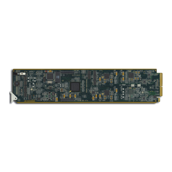
Page 26: Card Overview
Card Overview This section provides a general overview of the GPI-100 card components. Figure 3.1 GPI-100 — Components 1) Bypass Switch (SW1) 2) Menu Switch (SW2) 3) Reset Switch (SW3) 1. Bypass Switch (SW1) If the GPI-100 is installed in the MDL-R20 rear module, this two-position push-button can be used to control the relay. -
Page 27: Control And Monitoring Features
Control and Monitoring Features This section provides information on the card-edge LEDs for the GPI-100. Refer to Figure 3.2 for the location of the LEDs. POWER LED (DS1) BYPASS LED (DS2) Bypass Switch (SW1) PGM VIDEO IN LED (DS3) PGM VIDEO OUT LED (DS4) DS5 LED DS6 LED Menu Switch (SW2) - Page 28 Table 3.1 LEDs on the GPI-100 Color Display and Description When lit green, this LED indicates the Program Video input is Green present and valid. PGM VID IN (DS3) When lit red, this LED indicates that no valid input is present. This typically means that the input cable is disconnected.
-
Page 29: Configuration
Configuration In This Chapter This chapter explains how to use the user interface to set up the GPI-100. This discussion is based on the use of DashBoard through a network connection. The order of sections in this chapter follows the workflow required to set up the GPI-100 for operation. It is recommended that you proceed through the following sections in order to achieve the best possible understanding of the product. -
Page 30: General Settings
General Settings This section provides a summary of the initial tasks you may wish to perform before configuring your card for monitoring VANC data. Before proceeding to any of the other sections, please ensure that these settings are correct, as they will have an effect on the operation of the other functions. -
Page 31: Configuring Gpios
Configuring GPIOs The GPI-100 has eight GPIOs connections on the rear module. You can monitor the status of each of the inputs/outputs as either Low or High using the fields in the GPIO Status tab. This section outlines how to configure a GPIO to be active and if required, reverse its polarity. Configuring the GPIO Mask The GPIO Mask tab controls which of the eight GPIOs are active. - Page 32 To reverse the polarity of a GPIO 1. Select the GPIO Polarity tab. GPIO Polarity Tab 2. From the provided list, select the box(es) for the GPIOs you wish to invert the signal for. 3. Click Save to apply the changes. 4–4 •...
-
Page 33: Setting The Logging Timestamp
Setting the Logging Timestamp The GPI-100 logs any changes of the GPIO state for both the encode and decode cards. For the timestamp to be valid, you must have the time set on the GPI-100. There are three possible methods for setting the time; network time server, timecode or manually. To set the logging timestamp 1. -
Page 34: Downloading Log Files
Downloading Log Files The Log tab shows the last 20 trigger events. An event occurs any time there is a change to any of the GPIOs that are currently enabled. It is logged when a GPIO goes high and also logged when it returns to low. -
Page 35: Monitoring
Product Status The Product tab provides read-only information, such as board revision, serial number, and rear module type. This information is helpful to a Ross Video technical support when there are questions about the operation of the unit. Example of a Product Status Tab GPIO Status Tab The GPIO Status tab reports the status of the eight GPIO inputs/outputs. - Page 36 The following fields are displayed in the GPIO Status tab: • Card Status — This field reports if the GPIO connection are valid (green), or if no video source or unsupported rear module is connected. • Incoming ASI — This field reports the length and speed of the packet. •...
-
Page 37: Specifications
Specifications In This Chapter This chapter provides the technical specification information for the GPI-100. Note that technical specifications are subject to change without notice. The following topics are discussed: • Technical Specifications GPI-100 User Manual (Iss. 06) Specifications • 5–1... -
Page 38: Technical Specifications
Technical Specifications This section provides technical specifications for the GPI-100. Table 5.1 GPI-100 Technical Specifications Category Parameter Specification Number of Inputs 1 Program input 480i 59.94 (SMPTE 259M) 576i 50 (SMPTE 259M) 1080i 50, 59.94, 60 (SMPTE 292M) Data Rates and SMPTE Standards Accommodated 720p 50, 59.94, 60 (SMPTE 292M) 1080p 23.98, 24 (SMPTE 292M) -
Page 39: Service Information
Service Information In This Chapter This chapter contains the following sections: • Troubleshooting Checklist • Warranty and Repair Policy GPI-100 User Manual (Iss. 06) Service Information • 6–1... -
Page 40: Troubleshooting Checklist
Reset Button In the unlikely event of a complete card failure, you may be instructed by a Ross Technical Support specialist to perform a complete software reload on the GPI-100. -
Page 41: Warranty And Repair Policy
FIVE (5) years from the date of shipment from our factory. In the event that your GPI-100 proves to be defective in any way during this warranty period, Ross Video Limited reserves the right to repair or replace this piece of equipment with a unit of equal or superior performance characteristics. - Page 42 Contact Us Contact our friendly and professional support representatives for the following: • Name and address of your local dealer • Product information and pricing • Technical support • Upcoming trade show information Telephone: +1 613 • 652 • 4886 Technical After Hours Emergency: +1 613 •...
Need help?
Do you have a question about the openGear GPI-100 and is the answer not in the manual?
Questions and answers