Argo AFSI ECO 120SH3 Service Manual
Split type floor-standing air conditioner
Hide thumbs
Also See for AFSI ECO 120SH3:
- User manual and installation manual (50 pages) ,
- Service manual (122 pages) ,
- Manual (37 pages)
Table of Contents

Subscribe to Our Youtube Channel
Related Manuals for Argo AFSI ECO 120SH3


Summary of Contents for Argo AFSI ECO 120SH3
-
Page 1: Summary
SPLIT TYPE FLOOR-STANDING AIR CONDITIONER SERVICE MANUAL OUTDOOR UNIT INDOOR UNIT AFSI ECO 120HL AFSI ECO 120SH3 Please read this manual carefully before installing and using the air conditioner, and retain for future reference. V 04/21... -
Page 2: Table Of Contents
Table of Contents Part Ⅰ : Technical Information ...............1 1. Summary ........................1 2. Specifications ......................3 2.1 Specification Sheet ....................3 2.2 Capacity Curve in Different Outdoor Temperature ........7 2.3 Cooling Data Sheet in Rated Frequency ............7 2.4 Noise Curve ........................8 3. Outline Dimension Diagram ................9 3.1 Indoor Unit ........................9... - Page 3 Service Manual 8.5 Installation of Indoor Unit ..................29 8.6 Installation of Outdoor Unit ................33 8.7 Vacuum Pumping and Leak Detection ............35 8.8 Check after Installation and Test Operation ..........35 9.Troubleshooting ....................36 9.1 Judgement by Flashing LED of Indoor ............36 9.2 How to Check Simply the Main Part of Indoor ..........39 9.3 How to Check Simply the Main Part of Outdoor .........49...
-
Page 4: Part Ⅰ : Technical Information
Service Manual Part Ⅰ : Technical Information 1. Summary AFSI ECO 120HL Outdoor Unit: AFSI ECO 120SH3 Remote Controller: Technical Information... -
Page 5: Specifications
Service Manual 2. Specifications 2.1 Specification Sheet Parameter Unit Value AFSI ECO 120HL-AFSI ECO 120SH3 Model Product Code Rated Voltage 380- Power Rated Frequency Supply Phases Power Supply Mode outdoor Cooling Capacity 12500 Heating Capacity 13500 Cooling Power Input 3440... - Page 6 AFSI ECO 120SH3 Model of Outdoor Unit Product Code ZHUHAI LANDA COMPRESSOR Compressor Manufacturer/Trademark CO., LTD Compressor Model QXFS-F428zX450I Compressor Oil FW68DA or equivalent Compressor Type Rotary L.R.A. Compressor RLA Compressor Power Input 4060 Overload Protector Throttling Method Electron expansion valve Operation Temp ºC...
-
Page 7: Capacity Curve In Different Outdoor Temperature
Service Manual 2.2 Capacity Curve in Different Outdoor Temperature Cooling Heating Conditions Conditions Indoor: DB20°C/WB15°C Indoor: DB27°C/WB19°C Indoor air flow: High Indoor air flow: High Pipe length: 5m Pipe length: 5m Outdoor Temp.(°C) Outdoor Temp.(°C) 2.3 Cooling Data Sheet in Rated Frequency Cooling: Pressure of gas pipe Rated cooling condition(°C) -
Page 8: Noise Curve
2.4 Noise Curve Indoor side noise when blowing Outdoor side noise when blowing High Super High Middle Compressor frequency/Hz Indoor fan motor rotating speed Technical Information... -
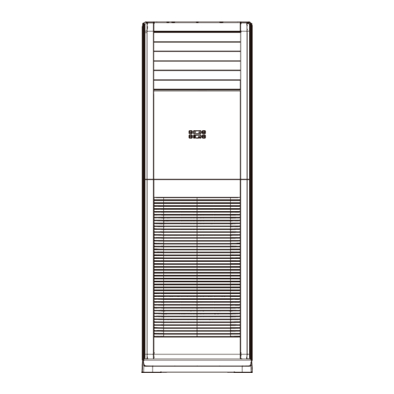
Page 9: Outline Dimension Diagram
3. Outline Dimension Diagram 3.1 Indoor Unit AFSI ECO 120HL Unit:mm Model 1882 Technical Information... -
Page 10: Outdoor Unit
3.2 Outdoor Unit AFSI ECO 120SH3 1028 Unit:mm Technical Information... -
Page 11: Refrigerant System Diagram
Valve Capillary Strainer Service Manual COOLING 4. Refrigerant System Diagram Outdoor unit Indoor unit Gas pipe side Valve 4-Way valve Di s charge Heat Suction Accumlator exchanger Compressor (evaporator) Heat exchanger Liquid pipe (condenser) side Valve Strainer Electronic Strainer expansion COOLING HEATING Connection pipe specification:... -
Page 12: Electrical Part
5. Electrical Part 5.1 Wiring Diagram ● Instruction Symbol Symbol Color Symbol Symbol Color Symbol Name Yellow Brown COMP Compressor Blue Grounding wire YEGN Yellow/Green Black ● Indoor Unit AFSI ECO 120HL Technical Information... - Page 13 ● Outdoor Unit AFSI ECO 120SH3 These wiring diagrams are subject to change without notice; please refer to the one supplied with the unit. Technical Information...
-
Page 14: Pcb Printed Diagram
Service Manual 5.2 PCB Printed Diagram Indoor unit ● Top view 1 Interface of live wire 2 Fuse Interface of communication wire for outdoor unit 4 Interface of netural wire 5 Motor interface of indoor unit 6 Interface of earthing wire Connection needle stand of display board 8 Left&right swing interface... - Page 15 Outdoor unit ● Top view Name Name Name Terminal of high pressure Terminal of compressor Terminal of inductance protection electric heating Terminal of low pressure Terminal of 4-way valve Terminal of neutral wire protection Terminal of compressor Terminal of outdoor fan Terminal of communication overload protection Terminal of outdoor...
-
Page 16: Function And Control
Service Manual 6. Function and Control 6.1 Function Buttons of Air Conditioner Button’s Name and Function ON/OFF button MODE button FAN button FUNCTION button ▼/▲ button ON/OFF button MODE FUNC. Introduction for icons on display screen of air conditioner Ambient temperature Timer Operation or set temperature... - Page 17 Button’s introduction ▼/▲ button After each pressing of "▲" or "▼" button, set temperature will increase or decrease . Temperature adjustment range is . This button is invalid under auto mode. Timer setting can be set in 1h increment among 0~24h. When it is adjusted to auxiliary heating function setting through Function button,press this button to turn on or turn off auxiliary heating.
-
Page 18: Remote Control Operations
Service Manual 6.2 Remote Control Operations Buttons on remote controller ON/OFF button SAVE button FAN button MODE button ▲/ button HEAT button COOL button button button SLEEP button WiFi button X-FAN/E-HEATER button QUIET button LIGHT button TIMER button Introduction for icons on display screen Set fan speed fan speed. - Page 19 ON/OFF button Press this button can turn on or turn off the air conditioner. After turning on the air conditioner, indoor unit will give out a sound. SAVE button Under cooling mode, press this button to start up or turn off energy-saving function.When energy-saving function is started up, "SE"...
- Page 20 Service Manual button Under simple swing mode, press this button can turn on (" " icon is displayed) or turn off (" " icon is not displayed) the left&right swing function. When the unit is turned off by remote controller, press "▲" button and " "...
- Page 21 QUIET button Press this button can turn on or turn off QUIET function. This function is not available for this unit. LIGHT button Press this button to turn off display light on indoor unit. Press this button again to turn on display light. TIMER button ▲...
-
Page 22: Description Of Each Control Operation
Service Manual 6.3 Description of Each Control Operation Note:Heating function is not available for this model. 1.Basic Functions 1.1 Cooling Mode When Tamb.≥Tpreset+1 , the unit will run in cooling mode. Meanwhile, compressor and outdoor fan will run. Indoor fan will run at setting fan speed;... - Page 23 3.3 Sleep If the controller is in cooling or dry mode, after the sleep function is started, Tpreset will be increased but it won’t increase over 3 . Then the unit will run at the increased temperature. If the controller is in heating mode, after the sleep function is started, Tpreset will be decreased and it won’t decrease over 3 .
-
Page 24: Ewpe Smart App Operation Manual
6.4 Ewpe Smart App Operation Manual Control Flow Chart Internet Cloud intelligent Home Wi-Fi Cellular/ home Other Wi-FI appliances Home wireless router Home Wi-Fi Operating Systems Requirement for User's smart phone: iOS system Android system Support iOS7.0 and Support Android 4.4 and above version above version Download and installation... -
Page 25: Part Ⅱ : Installation And Maintenance
Service Manual Part Ⅱ : Installation and Maintenance 7. Notes for Installation and Maintenance 10. If the power cord or connection wire is not long enough, Safety Precautions: please get the specialized power cord or connection wire from the manufacture or distributor. Prohibit prolong the wire by Important! yourself. - Page 26 Safety Precautions for Installing and Relocating the Unit: To ensure safety, please be mindful of the following precautions. Warnings 1. When installing or relocating the unit, be sure to keep the refrigerant circuit free from air or substances other than the specified refrigerant.
- Page 27 Service Manual Safety Operation of Flammable Refrigerant Qualification requirement for installation and maintenance man ●All the work men who are engaging in the refrigeration system should bear the valid certification awarded by the authoritative organization and the qualification for dealing with the refrigeration system recognized by this industry. If it needs other technician to maintain and repair the appliance, they should be supervised by the person who bears the qualification for using the flammable refrigerant.
- Page 28 Main Tools for Installation and Maintenance 1. Measuring tape 2. Screw driver 3. Impact drill, drill head, electric drill 4. Electroprobe 5. Universal meter 6. Torque wrench, open-end wrench, inner hexagon spanner 7. Electronic leakage detector 8. Vacuum pump 9. Pressure meter 10.
-
Page 29: Installation
Service Manual 8. Installation 8.1 Installation Dimension Diagram Away from wall (30cm at least for piping side) Away from obstacles Away from wall (30cm at least for piping side) Away from back side Installation and Maintenance... - Page 30 Installation procedures Start installation Preparation before installation Read the requirements select installation Prepare tools for electric connection location Select indoor unit Select outdoor unit installation location installation location Install the support of outdoor unit Drill wall holes (select it according to the actual situation) Connect pipes of indoor Fix outdoor unit unit and drainage pipe...
-
Page 31: Selection Of Installation Location
Service Manual 8.2 Installation Parts-checking 8.4 Requirements for electric connection Safety Precaution: Name Name 1.Must follow the electric safety regulations when installing the unit. Indoor unit Sealing gum 2.If the supply cord is damaged, it must be replaced by the Outdoor unit Wrapping tape manufacturer or its... - Page 32 Note: 1.Pay attention to dust prevention and take relevant Refer to the following table for wrench moment of force: safety measures when opening the hole. Hex nut diameter(mm) Tightening torque(N m) 2.The plastic expansion particles are not provided and Φ6.35(1/4") 15.7(1.6kg.m) should be bought locally.
-
Page 33: Installation Of Outdoor Unit
Service Manual 3. Adjust the position of upper and lower adjusting baffle; Step Eight: place the indoor unit clamp the connection pipe and drain pipe as firm as 1.Put the bound pipes in the wall pipe and then make them pass through the wall hole. - Page 34 2. Connect the drain hose into the drain vent.(As show in Fig.17) AFSI ECO 120SH3 NOTE: As for the shape of drainage joint,please refer to the current product.Do not install the drainage joint in the...
-
Page 35: Vacuum Pumping And Leak Detection
Service Manual 8.8 Check after Installation and Test 8.7 Vacuum Pumping and Leak Detection Operation Use Vacuum Pump 1. Check After Installation 1. Remove the valve caps on the liquid valve and gas valve Check according to the following requirement after finishing and the nut of refrigerant charging vent. -
Page 36: Troubleshooting
9.Troubleshooting 9.1 Judgement by Flashing LED of Indoor Malfunction Error A/C Status Possible Causes Name Code 1. The main board and the display panel are not connected well. 2. The OVC terminal on main board is not connected well with the high pressure switch on the complete unit. - Page 37 Service Manual Malfunction Error A/C Status Possible Causes Name Code 1. Main board of indoor unit is damaged; WIFI Loads operate normally, while the unit can’t 2. Detection board is damaged; communication be normally controlled by APP. 3. The connection between indoor unit and detection malfunction board is not good;...
- Page 38 Malfunction Error A/C Status Possible Causes Name Code 1. The wiring terminal between outdoor discharge The unit will stop operation as it temperature sensor and maiboard is loosened or poorly reaches the temperature point. Outdoor contacted; During cooling and drying operation, discharge 2.
-
Page 39: How To Check Simply The Main Part Of Indoor
Service Manual 9.2 How to Check Simply the Main Part of Indoor 1. High pressure protection (E1) Start Connect the display panel with the main board well Are the display panel and main board Malfunction is eliminated. connected tightly? Are the OVC terminal Connect the OVC terminal on the main board with on the main board connected Malfunction is eliminated. - Page 40 2. Freeze protection(E2) Start Clean the filter, check Is the problem Poor air return in indoor unit space at the top of solved? indoor unit Check whether jumper Is the problem The fan speed is abnormal cap and motor is solved? normal Is the problem...
- Page 41 Service Manual 3. Low pressure protection of compressor (E3) “E3" is displayed on the unit. Is the terminal Re-insert it tightly of low pressure switch to ensure reliable inserted well? contact. Is the malfunction eliminated? Is the system pressure higher than the acting Add refrigerant.
- Page 42 4. High discharge temperature protection of compressor (E4) Start Check the system; Problem is Abnormal system (blockage) eliminate the solved blockage Motor speed of Check wiring and Problem is outdoor unit is abnoral fan capacitor, solved (under cooling mode) replace motor Check the unit to Abnormal air in for Problem is...
- Page 43 Service Manual 5. Overcurrent protection (E5) Start Normal fluctuation is within 10% of the rated voltage on the Is the supply voltage unstable with big fluctuation? Malfunction is eliminated. nameplate Is the supply voltage too low with overload? Adjust the supply voltage to maintain it within normal range Malfunction is eliminated.
- Page 44 6. Malfunction of Temperature Sensor (F1, F2, F3, F4, F5) Troubleshooting for F1,F2 malfunction the wiring terminal between the temperature sensor and the controller loosened or poorly contacted? Insert the temperature sensor tightly Is malfunction eliminated Is there short circuit due to trip - over of the parts? Make the parts upright Is malfunction...
- Page 45 Service Manual 7. Communication malfunction(E6) If the unit operates normally before malfunction Check the connection wire according to the wiring diagram. Check built-in wiring If the connection wire of indoor and outdoor is connected well? unit Reconnect the wire or Replace the If the wiring is replace the connection...
- Page 46 8. High temperature and overload protection (AP1 below means control board of outdoor unit) E8 Main detection points: If the outdoor ambient temperature is in normal range; If the indoor and outdoor fan are running normally; If the radiating environment of indoor and outdoor unit is good. Malfunction diagnosis process: Start Normal protection, please use it...
- Page 47 Service Manual Troubleshooting for F0 malfunction Heat exchangers are Clean the heat exchangers and remove Malfunction is too dirty or the air inlet/outlet eliminated. blockage of air inlet/outlet. is blocked. Compressor doesn't work Malfunction is Make compressor run normally. normally. Strange noise or leakage occurs. eliminated.
- Page 48 10. Malfunction of detecting plate(WIFI) JF Start check if the connection wire are correctly connected detecting Replace the plate with the same model Is malfunction eliminated Replace the mainboard with the same model The end Installation and Maintenance...
-
Page 49: How To Check Simply The Main Part Of Outdoor
Service Manual 9.3 How to Check Simply the Main Part of Outdoor 1. E1: High pressure protection Malfunction description: The pressure of ODU high pressure side is too high. Main check points: a. Is the system pressure is normal; b. Is the pressure switch is normal; c. - Page 50 They should be almost the same, if they’re with big difference, the compressor is damaged, please check the insulation condition of three phases to the case. 11. HC: PFC protection Main check points: a. Check if the unit voltage input is normal; b.
-
Page 51: Maintenance Method For Normal Malfunction
Service Manual 9.4 Maintenance Method for Normal Malfunction 1. Air Conditioner Can't be Started Up Possible Causes Discriminating Method (Air conditioner Status) Troubleshooting Confirm whether it's due to power failure. If yes, No power supply, or poor After energization, operation indicator isn’t bright wait for power recovery. - Page 52 4. ODU Fan Motor Can't Operate Possible causes Discriminating method (air conditioner status) Troubleshooting Connect wires according to wiring diagram to Wrong wire connection, or poor Check the wiring status according to circuit make sure all wiring terminals are connected connection diagram firmly...
-
Page 53: Exploded View And Parts List
Service Manual 10. Exploded View and Parts List 10.1 Indoor Unit 36 35 The component picture is only for reference; please refer to the actual product. Installation and Maintenance... - Page 54 Part Code Description AFSI ECO 120HL Product Code Right Side Plate Sub-Assy 0130451801 Rear Plate Sub-Assy 01304290 Right Air Guard 01364507 Top Cover Sub-Assy 000051000034 Left Air Guard 01364506 Left Side Plate Sub-Assy 0130451901 Evaporator Assy 01100100275 Air Guard Assy 01364509 Chassis 200148000005...
-
Page 55: Outdoor Unit
Service Manual 10.2 Outdoor Unit 10 11 The component picture is only for reference; please refer to the actual product. Installation and Maintenance... - Page 56 Part Code Description AFSI ECO 120SH3 Product Code Front Grill 01572800003 Cabinet 012022000003 Diversion Circle 10474100003 Axial Flow Fan 1043410000801 Handle 2690410001603 Front Side Plate 012050060025 Drainage hole Cap 76715005 Drainage Joint 26113009 Compressor and Fittings 009001060059 Motor Support Sub-Assy...
-
Page 57: Removal Procedure
11. Removal Procedure Caution: discharge the refrigerant completely before removal. 11.1 Removal Procedure of Indoor Unit Step Procedure 1.Outside view of indoor unit 2.Remove air-in panel Open the screw cover, use screwdriver to remove screws used for fixing the air-in panel at both sides, and then remove the air-in panel. - Page 58 Service Manual Step Procedure 3.Remove filter, middle air-in panel Buckle Hold the buckle position at the upper part of the filter, and pull it upwards to Filter draw out the filter. Middle air-in panel Remove 2 screws at top part of the air- in panel, pull the middle air-in panel upwards and then remove the middle air-in panel.
- Page 59 Step Procedure 5.Remove air-out panel Screw Remove 3 screws at the top part of the air-out panel, 2 screw at the lower part and screws under the screw cover, push the air-output panel upwards slightly and then remove the air-output panel.
- Page 60 Service Manual Step Procedure 7.Remove display box Big front panel sub-assy Display box sub-assy Take out the display connection wire from the wire groove, remove 2 screw at the back of the display cover and then remove the display cover sub-assy. 8.Remove upper cover, air-outlet foam, guide louver, Upper swing blade...
- Page 61 Step Procedure 10.Remove air damper Remove 10 screws used for fixing the air damper, and then the air damper can be removed. Air damper 11.Remove electric heating part Air damper Remove 4 screws on the protective grille and then remove the protective grille; Remove 4 screws on the electric heating part and then remove the electric heating part.
- Page 62 Service Manual Step Procedure 12.Remove top cover Screw Top cover Remove 7 screws on the top cover, and then pull the top cover upwards to remove it. 13.Remove evaporator Screw Remove 3 screws on the evaporator, 2 screw at the middle part and 2 screws at the lower part.
- Page 63 Step Procedure 14.Remove propeller housing, centrifugal Propeller housing blade and motor Remove 3 screws used for fixing the press plate of propeller housing and then remove the press plate of propeller housing; Rotate the guide loop to a certain position along the clockwise direction, and then remove the guide loop;...
- Page 64 Service Manual Step Procedure 16.Remove left and right side plate sub-assys Right side plate sub-assy Remove screws at both sides, pull them to both sides respectively and then left and right plate sub-assys can be removed. L e f t s i d e p l a t e sub-assy Installation and Maintenance...
-
Page 65: Removal Procedure Of Outdoor Unit
Service Manual 11.2 Removal Procedure of Outdoor Unit Warning Be sure to wait for a minimum of 10 minutes after turning off all power supplies before disassembly. Steps Procedure 1. Remove big handle,valve cover and top cover handle Remove the screw connecting the big handle and right side plate, and then remove the big handle. - Page 66 Steps Procedure 3. Remove the front side plate Remove the 2 tapping screws fixing the front side pl front side plate. Take the front side plate outward to remove it. screws rear side plate sub-assy 4. Remove the rear side plate sub-assy Remove the screws connecting the rear side plate sub-assy...
- Page 67 Service Manual Steps Procedure 6. Remove grille and outer case outer case screws Remove the 4 screws connecting the grille and outer case, and then remove the panel grille. grille Remove the screws connecting the outer case with motor support, isolation plate and chassis; lift the outer case upwards;...
- Page 68 Steps Procedure 9. Remove 4-way valve assy and electric expansion valve 4-way valve assy sub-assy Unsolder the welding joints connecting the 4-way valve assy with electric expansion valvesub-assy, compressor and condenser; remove the 4-way valve. Note: Before unsoldering the welding joint, wrap the 4-way valve with a wet cloth completely to avoid damage to the valve caused by high temperature.
-
Page 69: Appendix
Service Manual Appendix: Appendix 1: Reference Sheet of Celsius and Fahrenheit Conversion formula for Fahrenheit degree and Celsius degree: Tf=Tcx1.8+32 Set temperature Fahrenheit Fahrenheit Fahrenheit display Fahrenheit display Fahrenheit display Fahrenheit Celsius (℃) Celsius (℃) Celsius (℃) (℉) (℉) (℉) temperature temperature temperature... -
Page 70: Appendix 3: Pipe Expanding Method
Appendix 3: Pipe Expanding Method Pipe Note: Pipe cutter Improper pipe expanding is the main cause of refrigerant leakage.Please expand the pipe according to the following steps: Leaning Uneven Burr A:Cut the pip ● Confirm the pipe length according to the distance of indoor unit and outdoor unit. ●... -
Page 71: Appendix 4: List Of Resistance For Temperature Sensor
Service Manual Appendix 4: List of Resistance for Temperature Sensor Resistance Table of Ambient Temperature Sensor for Indoor and Outdoor Units(15K) C) Resistance(kΩ) C) Resistance(kΩ) Resistance(kΩ) Resistance(kΩ) Temp( Temp( Temp( Temp( 138.1 18.75 3.848 1.071 128.6 17.93 3.711 1.039 121.6 17.14 3.579 1.009... - Page 72 Resistance Table of Tube Temperature Sensors for Outdoor and Indoor(20K) C) Resistance(kΩ) C) Resistance(kΩ) Resistance(kΩ) Resistance(kΩ) Temp( Temp( Temp( Temp( 181.4 25.01 5.13 1.427 171.4 23.9 4.948 1.386 162.1 22.85 4.773 1.346 153.3 21.85 4.605 1.307 20.9 4.443 1.269 137.2 4.289 1.233 129.9...
- Page 73 Service Manual Resistance Table of Discharge Temperature Sensor for Outdoor(50K) C) Resistance(kΩ) Resistance(kΩ) C) Resistance(kΩ) Resistance(kΩ) Temp( Temp( Temp( Temp( 853.5 18.34 4.75 799.8 93.42 17.65 4.61 89.07 16.99 4.47 703.8 84.95 16.36 4.33 660.8 81.05 15.75 4.20 620.8 77.35 15.17 4.08 580.6...
- Page 74 REGULATION (EU) No. 517/2014 - F-GAS The unit contains R32, a fluorinated greenhouse gas with global warming potential (GWP) = 675. Do not release R32 into the atmosphere. AFSI ECO 120SH3 – Kg. 2,6 = 1,76 Tonn CO2 equiv. www.argoclima.com...
Need help?
Do you have a question about the AFSI ECO 120SH3 and is the answer not in the manual?
Questions and answers