
Related Manuals for Sartorius BioPAT Trace


Summary of Contents for Sartorius BioPAT Trace
- Page 1 Operating Instructions BioPAT Trace | Multi Trace ® 2- | 2 × 4-Channel Online Analysis System 85032-541-53...
-
Page 3: Table Of Contents
Contents Contents 1 About this Document . . . . . . . . . . . . . . . . . . . . . . . . . . . . . . . . . . . . . . . . . . . . . . . . . . . . 8 Introduction . - Page 4 Contents Accessories for Sampling Probes ........24 3.8.1 Accessories for Dialysis Probe .
- Page 5 Contents Installing the Software ..........66 Changing the Start Settings .
- Page 6 Contents Tips ..............110 8.5.1 Choosing Suitable Standard Solutions .
- Page 7 Contents 12 Storage and Shipping . . . . . . . . . . . . . . . . . . . . . . . . . . . . . . . . . . . . . . . . . . . . . . . . . . 127 12.1 Storage .
-
Page 8: About This Document
About this Document About this Document Introduction These instructions provide all the information necessary for operation of the BioPAT Trace | Multi Trace (hereinafter referred to as the device). ® The instructions must be read, understood and used by all personnel using the device. -
Page 9: Target Groups
About this Document Target Groups These instructions are designed for the following target groups. The target groups must possess the knowledge listed. Target group Knowledge | responsibilities User The user is familiar with the operation of the device and the associated work processes. He knows the dangers that can occur when working with the device and can avoid these dangers. -
Page 10: Symbols Used
About this Document Symbols Used 1.4.1 Warnings in Operation Descriptions WARNING Denotes a danger with risk that death or severe injury may result if it is not avoided. CAUTION This symbol denotes a possible danger with risk that moderate or minor injury may result if it is not avoided. -
Page 11: Safety Instructions
Safety Instructions Safety Instructions Intended Use The device is used for online monitoring of the analytes glucose, lactate, methanol and ethanol in laboratory or industrial cultivations of micro- organisms and cell lines. The device may only be used indoors. These instructions are part of the device. The device is intended exclusively for use in accordance with these instructions. -
Page 12: General Safety Instructions
Work on and modifications to the electrical equipment of the device may only be carried out by Sartorius Service personnel. The device may only be opened by Sartorius Service personnel. Check the device regularly for defects, such as loose connections or damage to the insulation. -
Page 13: Accessories, Consumables, And Spare Parts
— Malfunction of the device — Total failure of the device Only use accessories, consumables, and spare parts from Sartorius. Sartorius can provide information on operational quality upon request. Only use accessories, consumables, and spare parts that are in technically perfect condition. -
Page 14: Biopat ® Trace | Multi Trace Product Description
BioPAT Trace | Multi Trace Product Description ® BioPAT Trace | Multi Trace ® Product Description The BioPAT Trace | Multi Trace analysis system is used for simultaneous ® online monitoring of the analytes glucose and lactate in laboratory or industrial cultivations of microorganisms and cell lines. -
Page 15: The Basics Of Electrochemical Measuring Technology
BioPAT Trace | Multi Trace Product Description ® The Basics of Electrochemical Measuring Technology An electrochemical detector measures the current produced at a specific potential applied to the electrodes by the analytes in a flow conductivity cell. In the presence of an electrolyte solution, the electrochemical conversion of the substance at the working electrode leads to the release or attraction of... -
Page 16: Biosensor Principle
BioPAT Trace | Multi Trace Product Description ® Biosensor Principle The analytes glucose and lactate are detected by means of enzymatic reac- tions. Figure 1 shows the enzymatic conversion of glucose to gluconolactone. In the presence of water, gluconolactone is immediately hydrolyzed to glu- conic acid. -
Page 17: Fluidic System And Sampling
BioPAT Trace | Multi Trace Product Description ® The BioPAT Trace | Multi Trace biosensors consist of platinum thick-film ® electrodes that are durably coated with the corresponding enzymes (glucose oxidase (GOD) or lactate oxidase (LOD)). Then, enzyme and electrode are in close proximity to each other, so that the reactions described above can be recorded directly. - Page 18 BioPAT Trace | Multi Trace Product Description ® Conditioning of the sample is based on the method of flow diffusion analysis (Figure 4). This method works with a time-dependent sample transfer. For that purpose, the measurement line and the sample and |or the sample infeed are separated from each other by a membrane.
- Page 19 BioPAT Trace | Multi Trace Product Description ® When this segment is released by re-switching the valve, the flow goes to the conductivity cell, where it generates a signal. The intensity of the signal is a measure of the concentration of the sample. One big advantage of this enrichment method is the very broad measuring range that is achieved by varying the diffusion time;...
-
Page 20: Data Transmission And Data Saving
BioPAT Trace | Multi Trace Product Description ® Adjusting the PID Controller The principle of the PID controller is known since 1922 (Minorsky[1]), but useful rules for adjustment were not available before 1942 (Ziegler and Nicols[2]). Today most of the controller will be adjusted by empirical design. This design can also be used in the field of biotechnology. -
Page 21: Consumables
BioPAT Trace | Multi Trace Product Description ® Consumables 3.6.1 BioPAT Trace | BioPAT Multi Trace Tubing Set ® ® Description Order no . Dialysis tubing set, glucose application | lactate BPT0089 Dialysis tubing set (ethanol | methanol) BPT0050 Enzyme reactor for ethanol | methanol application BPT0048 Dialysis tubing set, glucose application | lactate for BPT0M07... -
Page 22: Calibration Standard Solutions (Contents: 0.5 Liters)
BioPAT Trace | Multi Trace Product Description ® 3.6.4 Calibration Standard Solutions (contents: 0.5 liters) Description Order no . Calibration standard 0.1 g/L glucose, 0.05 g/L lactate BPT0043 Calibration standard 0.5 g/L glucose, 0.25 g/L lactate BPT0011 Calibration standard 1 g/L glucose, 0.5 g/L lactate BPT0010 Calibration standard 2 g/L glucose, 1 g/L lactate BPT0009... -
Page 23: Membranes
BioPAT Trace | Multi Trace Product Description ® 3.6.5 Membranes Description Order no . Membranes (glucose | lactate, higher measuring range) BPT0024 for the dialysis probe (contents: 5 pcs) Membranes (glucose | lactate, lower measuring range for BPT0024LR the dialysis probe (contents: 5 pcs) Membranes (glucose | lactate/cellulase-stabile) for the BPT0040 dialysis probe (contents: 5 pcs) -
Page 24: Accessories For Sampling Probes
Autoclaving caps BPT0081 Adapter 25/12 mm for the installation of the dialysis probe BB-38242540 165 mm in the 25 mm side port (Sartorius Safety port 52 mm) incl. O-rings Adapter 19/12 mm for installation of the dialysis probe into BB-8848630 the 12-mm cover port (M26x1); incl. O-ring Adapter 19/12 mm for installation of the dialysis probe into... -
Page 25: No Integrated Luer-Lock Connection)
BioPAT Trace | Multi Trace Product Description ® 3.8.2 Accessories for Dialysis Probe (1st generation, no integrated Luer-Lock connection) Description Order no . Dialysis probe installation kit BPT0045 Replacement sterilisation loop (contents: 5 pcs) BPT0071 Replacement adapter UNF-Luer connection for the BPT0072 dialysis probe Accessories for the BioPAT... -
Page 26: Design And Function
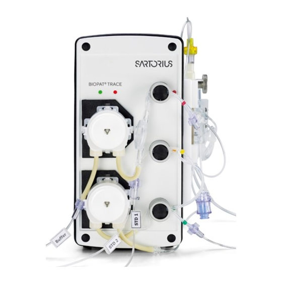
Design and Function Design and Function Setting Up the Device The BioPAT Trace | Multi Trace is an online analysis system in a compact ® metal housing. Communication with the user is driven by an external com- puter. As shown in the following figures, the front and side panels are equipped with the elements of the pre-assembled tubing set for analysis. - Page 27 Design and Function Side view of the device with the following components: Fig. 7: Components Pos . Component Conductivity cell Knurled nut for fastening the conductivity cell Diffusion module Drip counter Rinsing line with return valve In the diffusion module (6), a segment of the transport buffer is enriched with the analyte from the donor stream.
- Page 28 Design and Function Rear view of the device with the following elements: Figure 8 shows the rear view of the BioPAT Trace | Multi Trace. The device ® can be switched on and off by pressing the On/off switch (9). Using the calibration data, the electrochemical signal of the biosensor is converted internally to a concentration value.
-
Page 29: Biopat ® Trace | Multi Trace Measurement Methods
Design and Function The BioPAT Trace | Multi Trace can optionally be attached to laboratory ® stands, suspension bars or benchtop stands. A corresponding stand clamp and a suitable benchtop stand are available as accessories. CAUTION Risk of damage due to incorrect connection! Under no circumstances should a voltage source be connected to the analog data outputs at the rear of the BioPAT Trace | Multi Trace. -
Page 30: Dialysis Measuring Method Using The Dialysis Probe
Design and Function A more detailed explanation of the sampling probes can be found in Chapter “4.6 Dialysis Probe Function”, page 36. Fig. 9: BioPAT Trace | Multi Trace – System Setup ® 4.2.1 Dialysis Measuring Method Using the Dialysis Probe The dialysis measuring method using the dialysis probe involves the transfer of analytes through a dialysis membrane in the dialysis probe which separates the reactor contents (medium) from the acceptor stream. - Page 31 Design and Function The upper part of the flow system represents the donor stream, which is responsible for the infeed of the calibration solution into the diffusion module. Depending on the task at hand, the carrier stream accumulates the analyte in the diffusion module or in the dialysis probe. Valve 3 Liquid Waste Calibration Standard 1...
- Page 32 Design and Function For the dialysis method, the internal diffusion module is used to calibrate the BioPAT Trace | Multi Trace. By contrast, the dialysis probe in the bioreactor is ® always used for measuring the sample. A reference factor between the two membranes is then determined once.
-
Page 33: Conductivity Cell Function
Design and Function Conductivity Cell Function The conductivity cell contains biosensors for glucose and lactate or methanol/ethanol. The conductivity cell is shown in the figure on the left. The fluid inlet flow runs perpendicular to the 2-channel sensor (“wall jet” principle). It is possible to check that the flow through the cells is free from air bubbles by using the viewing window. -
Page 34: Particle Filter Function
Design and Function If air bubbles are present in the conductivity cell after connecting the dialysis probe, then it would be advantageous to operate the system in measurement mode with maximum measuring frequency for a period of approx. 30 minutes. CAUTION Erroneous calibrations due to air bubbles! If there are air bubbles in the measuring cell, under no circumstances should calibrations or reference measurements be carried out, as these may be... -
Page 35: Diffusion Module Function
Design and Function Diffusion Module Function The diffusion module is part of the tubing set. The standard solutions or an external sample are pumped through the diffusion module to the analysis system. A membrane enables diffusion of the substrate from the donor solutions (both standard and sample) into the buffer solution (acceptor). -
Page 36: Dialysis Probe Function
Design and Function Dialysis Probe Function If a dialysis probe is used to feed the sample from Loaded Unloaded the bioreactor into the BioPAT Trace | Multi Buffer stream ® Trace, then the analyte is transferred through a diffusion membrane into an internal pump- driven buffer stream and transported to the conductivity cell. -
Page 37: Enzyme Reactor Function
Design and Function Enzyme Reactor Function The enzyme reactor is required for measuring methanol and ethanol. Inside the reactor is the immobilized enzyme alcohol oxidase (AOD). There, the corresponding alcohol is converted and hydrogen peroxide is formed. The hydrogen peroxide is then detected in the conductivity cell. CAUTION High temperatures can destroy the enzyme! Due to the stability of the enzyme used, the... -
Page 38: Transport
Transport Transport The BioPAT Trace | Multi Trace including ® accessories is delivered in protective packaging. Please save this packaging; proper shipping is only possible in the original packaging. Upon receipt, check the delivery for completeness and any possible damage that may have occurred in transit. -
Page 39: Initial Installation
Initial Installation Initial Installation Setup 6.1.1 Device Setup The BioPAT Trace | Multi Trace must be setup near the bioreactor you want ® to monitor (at max. distance of 2 m). The location must be free of vibrations and protected against corrosive atmospheres and chemical contamination. Additionally, the BioPAT Trace | Multi Trace should be protected against ®... - Page 40 Initial Installation 6.1.1.1 Preparing the Transport Buffer The transport buffer is a salt mixture (for cell cultures) or a concentrate (for microbial cultures) and must be dissolved or diluted with water (deionized or distilled) according to the instructions. Proper dilution can be checked by measuring the conductivity of an aliquot.
-
Page 41: Tubing Set Connectors On The Device
Initial Installation Dialysis mode Interval Buffer consumption 10 L for: µl/min ml/h ml/d 141.3 203.5 1,179 127.0 182.8 1,313 112.6 162.2 1,480 CAUTION Erroneous measurements due to tubing sets not being filled or only being partly filled! Before filling the tubing set, make sure that tubing is connected to all solutions and that the vessels are sufficiently filled. - Page 42 Initial Installation Fig. 12: BioPAT Trace tubing set dialysis ® In addition, the dialysis tubing set is provided with a single-use syringe with three-way stopcock for analyzing external samples. Fig. 13: BioPAT Multi Trace tubing set dialysis ® BioPAT Trace | Multi Trace Operating Instructions ®...
- Page 43 Initial Installation The connectivity cell with the built-in biosensor is supplied separately. It must be connected at the designated points (see arrows in Figures 12 and 13) using Luer connectors. The connection is protected from becoming mixed up by one male and one female Luer connector. Fig.
- Page 44 Initial Installation CAUTION Line Blockage When connecting the connectivity cell, it is essential to ensure that the tubing line protruding from the male connector on the tubing set is carefully inserted into the female connector of the connectivity cell. Otherwise, the line may become blocked, leading to incorrect measurement results! The lines for buffers, standards, sampling probe and waste are premounted and packaged in foil bags.
- Page 45 Initial Installation The inlet and outlet lines of the tubing set are packaged in foil bags and labeled. The individual tubes are affixed with the following labels: — BUFFER Connection to the transport buffer — WASTE Connection to waste — – Probe port 1 dialysis —...
-
Page 46: Attaching The Tubing Set For The "Dialysis
Initial Installation 6.1.3 Attaching the Tubing Set for the “Dialysis” Operating Mode Before attaching the filtration tubing set, the valve tubes must first be inserted into the pinch valves. To keep them from getting mixed up, each line is color-coded. The following rules apply: —... - Page 47 Initial Installation Now place the guidance plates on the valves such that the pair of tubes are positioned on their corresponding valve slots. When inserting the tubing, make sure that the red, yellow and green color coding is always located to the right of the valve and matches that valve’s color coding.
- Page 48 Initial Installation After you are done fitting all three valves, push both guidance plates towards the valve in order to secure the position of the tubes in the valve slot. As the next step, install the two pump cassettes on the motor shaft and press on the retaining plate firmly until you hear an audible click indicating that it has locked in.
- Page 49 Initial Installation Verify the proper placement of the pump cassettes. After installing the pumps and valves on the front of the device, attach the sensor, drip chambers and diffusion module to the side panel. The adjacent figure shows a completely assembled side panel.
- Page 50 Initial Installation Leverage the conductivity cell up onto the contact plug. While doing so, pull the upper retaining plate slightly upwards. Press the conductivity cell onto the holder and slide the retaining plate downwards. The conductivity cell is fastened to the device by tightening the knurled nut.
- Page 51 Initial Installation Fig. 17: BioPAT Multi Trace tubing set dialysis ® The connectivity cell with the built-in biosensor is supplied separately. It must be connected at the designated points (see arrows in Figure 1) using Luer connectors. The connection is protected from becoming mixed up by one male and one female Luer connector.
- Page 52 Initial Installation Afterwards, the rest of the components must be attached to the device. Using the holding slit on the side, fasten the diffusion module to the mounting rail. Make sure that the diffusion module is properly aligned with the arrow pointing upwards.
- Page 53 Initial Installation Finally, the connectivity cell line (male Luer connector) is connected to the orange safety valve on the drip chamber of the waste line. Additional Information In addition, the dialysis tubing set is provided with a single-use syringe with three-way stopcock for analyzing external samples.
-
Page 54: Installing The Tubing Set For The Biopat
Initial Installation 6.1.4 Installing the Tubing Set for the BioPAT Multi Trace ® The Multi Trace tubing set is inserted in the same way as the steps described previously (for BioPAT Trace). ® Then the additional tubes are mounted. 6.1.5 Connection and Removal of the Enzyme Reactor In the methanol/ethanol operating mode, an... - Page 55 Initial Installation Prior to installing the reactor, the tubing set must be inserted into the BioPAT Trace | Multi Trace ® and filled with buffer. Dry setup may reduce the reactor capacity and should therefore be avoided under all circumstances. First, start the filling process to fill the tubing set (see Chapter 7, page 73).
-
Page 56: Connecting The Dialysis Probe
Initial Installation After installing the enzyme reactor, follow the instructions on the monitor and the filling process will continue with the installed enzyme reactor. NOTICE For further usage, the enzyme reactor must be removed from the tubing set, filled with transport buffer and stored in the refrigerator at 4–8°C. If air enters into the enzyme reactor, there is the danger of a decrease in the capacity of the enzyme reactor resulting in lower sensitivity. -
Page 57: Mounting The Membrane In The Dialysis Probe
Initial Installation 6.2.1 Mounting the Membrane in the Dialysis Probe Install a new membrane before every online measurement involving bioprocesses with sterile feeds as shown in Figure 14. If this rule is not observed, a lack of sterility may jeopardize the entire cultivation process. Fig. -
Page 58: Ethanol In The Dialysis Probe
Initial Installation To assemble, proceed as follows: Insert the new membrane into the lower part of the dialysis probe. Ensure that the white side of the membrane points in the direction of the dialysis probe (in contact with the buffer) and the colored side of the membrane points in the direction of the probe lunette (in contact with the medium). -
Page 59: Installing The Dialysis Probe Into The Bioreactor
Initial Installation 6.2.3 Installing the Dialysis Probe into the Bioreactor Fit the friction washer (2) and O-ring (3) to the dialysis probe (3). NOTICE Note the 5-cm minimum immersion depth of the dialysis probe in the bioreactor, otherwise this could lead to incorrect readings. Install the dialysis probe on the bioreactor. - Page 60 Initial Installation Seal the dialysis probe (1) with the cover caps (2). This will prevent one-sided overpressure from occurring at the membrane in the dialysis probe, which could damage the membrane. Sterilize the dialysis probe NOTICE Dry sterilization is not suitable, as the membrane can become damaged.
-
Page 61: Connecting The Dialysis Probe To The Tubing Set
Initial Installation 6.2.5 Connecting the Dialysis Probe to the Tubing Set When connecting the probe to the tubing set, ensure that as little air as possible enters the tubing set, as this is in the form of small air bubbles, e.g. could get stuck in the measuring cell and lead to fluctuating readings. -
Page 62: Cleaning The Dialysis Probe And Replacing The Membrane
Initial Installation As a general rule, air bubbles in the tubing set are flushed out over time. However, this process takes a certain amount of time (e.g. during the priming process). If there are air bubbles in the measuring cell after connecting the dialysis probe, then proceed as follows: Operate the system for a period of 30 minutes in measurement mode with maximum measuring frequency. -
Page 63: Loading The Software And Network Connection
Initial Installation Loading the Software and Network Connection The BioPAT Trace | Multi Trace is run internally ® by a computer and can be operated as a full- ranked member in intranets and LANs, or can be directly interfaced with a PC. In order to do this, the operating software supplied must be installed on the designated PC. - Page 64 Initial Installation First download the other important files for the rest of the installation onto your computer by clicking the right mouse button. They can be found in the “Download” menu item. The following files can be found here: — setup_tracemon_x_x_x as setup file of the operating software (_x_x_x = version number) —...
- Page 65 Initial Installation If you would like to work via a LAN or intranet, the factory-set network address or the network name may not be compatible with your network. If this is the case, please contact your network administrator and change the BioPAT Trace | ®...
-
Page 66: Troubleshooting
Initial Installation 6.4.1 Troubleshooting If you have entered different or incorrect IP addresses on the device website and during the installation, it will not be possible to establish a connection. The following options are available: First, attempt to produce a connection to the internal device website via the standard IP address 192.168.120.231 using a direct PC connection and a cross-over Ethernet cable. -
Page 67: Changing The Start Settings
Initial Installation Changing the Start Settings If you changed the IP address at a later time, you should also update the startup settings in the program shortcut of the startup icon so that the device will continue to connect automatically. To do so, complete the following steps: Switch the screen view to your desktop. -
Page 68: Active Access Restriction | Log In
Initial Installation Active Access Restriction | Log in To activate the access restriction – by means of which the menu functions are assigned to the various responsible operators – the access privileges can be adjusted using the Login start command “-L”. The device opens then when you first start the administrator mode. -
Page 69: Assignment Of Analog Outputs
Initial Installation Assignment of Analog Outputs The measured values remain available for further use as analog signals at the ports analog 1 and analog 2. When using the ethanol | methanol method, the signal is output on analog 1. The output analog 3 is not assigned. Measuring Measuring channel... -
Page 70: Checklist For Starting-Up Operation
Initial Installation Checklist for Starting-up Operation Work step Function Chapter Page Status Install PC software (only on initial setup) Access website of the device 63ff Download installation program 63ff Start installation program Adjust IP address and subnet screen Prepare probes 56ff Install membrane 57ff... - Page 71 Initial Installation Work step Function Chapter Page Status Connect inlet and outlet lines 6.1.2 Connect tubing to transport buffer Connect tubing to calibration solutions Connect waste line to waste container Switch on device Switch on On/off switch on rear of the device Wait for internal computer to boot (white LED turns red) Start PC software...
- Page 72 Initial Installation Work step Function Chapter Page Status Starting the measurements 8.1.1 Confirm “Fill” button and wait for 75ff calibration Alternatively: Activate the “Start 75ff autom.” option – device starts measurement automatically after filling and calibration For methanol | ethanol only: 6.1.5 Connect enzyme reactor Einbau des Enzymreaktor in das...
-
Page 73: Startup
Startup Startup Startup Before every startup, check the BioPAT Trace | Multi Trace to make sure that ® all modules installed on the device are functional. The following conditions must be checked scrupulously on the device: — Are the two original pump cassettes installed properly? —... -
Page 74: Decommissioning
Startup Decommissioning The device can be switched off at any time by pressing the On/off switch. The calibration and reference values last stored remain in memory for the next start (see Chapter “8.3.1.1 Connect”, page 84). If the measuring instrument is not operated for two days (e.g. over the weekend), the buffer-filled system may remain standing. -
Page 75: Operation
Operation Operation Switch on the BioPAT Trace | Multi Trace at the ® On/off switch located on the rear panel and run it on an external PC. You will find the start icon on the PC’s desktop . Double-clicking it will start the application. - Page 76 Operation Every time the device restarts, completely fill the tubing set and run several preliminary measure- ments to render the sensor system stable before initiating the calibration routine. This process is called priming; alongside filling and preliminary measurements, it also includes an initial calibra- tion of the system.
- Page 77 Operation When the system is ready to run the measurement, the status message “In standby” in the lower right will appear. When the priming is completed, a panel for context based selection buttons is available. In dialysis mode, a third button labeled “Reference”...
-
Page 78: Basic Commands
Operation Basic Commands 8.1.1 Start The “Start” command starts the measurements of the analyser. The command can either be triggered directly by pressing the “Start” button or by a corresponding entry in the schedule (see Chapter “8.3.8.1 Events”, page 97). In this case, the command will only be executed when the specified time is reached. -
Page 79: Single Sample
Operation 8.1.4 Single Sample This function can be used for a spontaneous unscheduled single point mea- surement at a selected port (Multi Trace). This function is especially useful during long intervals, when for instance an actual value of a certain reactor is wanted. - Page 80 Operation The comparison is activated as follows: After clicking the “Reference” button, the device determines the concentration values in the reactor and suggests the corresponding values. Now, using a reference sample, you must check whether these values are correct and correct them accordingly.
- Page 81 Operation If no off-line analyzer is available for determining reference values, you can also measure the sample on the BioPAT Trace | Multi Trace. ® To do so, select the “Measurement” function and follow the further instructions prompted by the menu navigation. Draw a cell-free sample from the bioreactor (at least 5 mL) into a 5 mL syringe and connect it to the three-way stopcock.
-
Page 82: Fast Reference (Only For Dialysis)
Operation NOTICE Make sure that the three-way stopcock is set as displayed. Otherwise all following calibrations will be erroneous and the resulting measurements incorrect! Before you continue working, make sure that the three-way valve was set back to the initial position after removing the external sample, so that you can correctly measure Standard 1 during the next calibration. -
Page 83: Menu Bar
Operation The “Fast Reference” option allows a faster implementation of the reference measurement, in which the known concentration values of the medium can be entered before the actual reference measurement. After pressing the “Fast Reference” button, the input window appears. Now enter the corresponding concentration values and confirm with “Apply”. -
Page 84: Menu Item "Device
Operation If you want to create a new file, select the menu item “New”. If you want to load and display measured data from an old file, select the menu item “Load…”. The saved files can be easily processed, e.g. in Excel. - Page 85 Operation Once you have entered the correct IP address and the device is acknowledged by the network, it will connect to the control PC. An asterisk appears in the view bar behind the name or number of the device. Alternatively, you can start a search for new devices on the network by clicking on the button “Who is out there?”.
- Page 86 Operation This option starts an automatic cleaning proce- dure, including a 5-fold cycling of the priming mode. Afterwards, both pumps flush the tubing set at the low flow rate of the standby mode. For a new start, you must go to the menu item “Startup”...
-
Page 87: Menu Item "Display
Operation By clicking on the button “Continue measure- ment”, the system switches directly to opera- tional mode. No rinsing cycles or calibrations will be carried out. The former calibration values will be retained. NOTICE Do not activate “Continue measurement” unless you are certain that the same conditions prevail as before the pause (e.g. -
Page 88: Calibration Values
Operation 8.3.4 Calibration Values When the menu item “Calibration values” is selected, a window opens that shows the current calibration values. The axis intercepts (a0), calibration gradient (a1) and the reference factors (Reference fr) are displayed. Activating the option “Reset reference” resets the reference factors to the factor 1.0 (only in dialysis mode). -
Page 89: Settings
Operation The number of pending group measurements (or preliminary measurements) is displayed in field 1. In field 2, a current time count counts down the time until the end of the current action (in sec- onds). The remaining time in the interval of the measurement period is displayed in field 3 (in seconds). - Page 90 Operation 8.3.7.1 Parameters All relevant parameters for measuring operations can be configured in the “Parameters” sub-item. Measurement Period Enter the desired measuring interval here. When the value 1 is entered, measurement is performed every minute or at the maximum frequency. If one analysis should be per- formed every hour, then enter 60.
- Page 91 Operation Number of Measured Values in Groups When using larger measuring intervals, it can make sense to run several measurements with maximum frequency in quick sequence at a given point of time. This way, for example, a group of 10 measurements may be carried out every 6 hours.
- Page 92 Operation By pressing the “Calibration” button, you can ini- tiate a calibration at any time. Any changes made to the automatic calibration data during running operations are not valid until the next calibration. Measurements Per Standard This function is used to set the number of measurements per calibration standard.
- Page 93 Output of the serial data protocol is activated by the following tasks: Select [TRACE SeMDaP] for the parameter Select [ON] for [TRACE SeMDaP] For further details on protocol, please contact Sartorius Service. BioPAT Trace | Multi Trace Operating Instructions ®...
- Page 94 Operation 8.3.7.2 Test Ports For the BioPAT Multi Trace version the unit has 4 different test ports ® (bioreactor probes 1–4). These are controlled by the selection valves on the side of the device. In the case that not all four measuring probes are intended to be used, the respective activation of each port can be specified using the tag input window.
- Page 95 Operation 8.3.7.3 Basic Settings In the “Basic Settings” menu item, you can enter data that is important for carrying out and docu- menting the measurements. Before running the measurement, you can enter the project name and device location. This infor- mation will later be displayed in the header enabling a better assignment of data to the pro- cess, especially if several devices are in operation...
-
Page 96: Menu "Schedule
Operation 8.3.7.4 Language You can select your preferred language under the “Language” menu item. German, English, French, Spanish, Italian and Chinese are available. 8.3.8 Menu “Schedule” Using the menu “Schedule”, the device can be individually programmed in its temporal actions. The schedule is divided into the sections “Events”... - Page 97 Operation 8.3.8.1 Events In the submenu “Events”, individual actions are entered at certain times. For every action (one shot measurement, calibration, start, standby) one or more time points can be determined. These events are always handled in priority to other actions (from the schedule or the parameter list). In the event that the scheduled time of an action is conflicting with an action of the schedule or in the parameter list, it will wait until this is finished.
- Page 98 Operation By pressing the “Apply” button, the settings selected are transferred to the right list box and arranged chronologically. The entry can be marked by click- ing on a line and removed from the list again by pressing “Delete”. Double entries will be ignored, or at the same time entries only the command above is processed.
- Page 99 Operation The workflow is enabled by a check mark “Workflow active” in the selection box. If this box is not checked, the measurement processes in the parameter list are processed instead. The selected action for the first time interval in line 1 is active only during the second pass of the list.
-
Page 100: Menu "Controller
Operation 8.3.9 Menu “Controller” The integrated controllers (PID Controller and Minimum-Maximum Controller) can be configured and operated in the menu “Controller”. The controllers can directly drive external pumps (via the serial interface or analog output 3 on the back of the device) as feeding pumps. - Page 101 Operation If “Controller active” is selected, the built-in device controller is switched on and the feeding pump is activated. While the controller is active, the pump cannot be switched off or operated manually. To disable the controller, the check mark must be clicked.
- Page 102 Operation The respective type of control can be selected between PID Controller and Minimum-Maximum Controller in the sub menu “Parameters” under “Type of controller”. 8.3.9.1 PID Controller After selecting the type of controller to PID Controller in the submenu “Parameters” the “Set-point Glucose”...
- Page 103 Operation In order to avoid a too high influence of the integral gain on the controller at the beginning, the integral gain can be reset to the preset value by “Reset controller” at any time. This command must then be confirmed with “Ok”. CAUTION Always reset the controller after filling the feeding line or with unknown history to avoid...
- Page 104 Operation 8.3.9.2 Minimum-Maximum Controller After selecting the type of controller to Mini- mum-Maximum Controller in the submenu “Parameters” the “Minimum” and “Maximum” limits are registered for the control. The Minimum-Maximum Controller switches the feeding pump if it is above or below the limits respectively to the minimum flow rate, or maxi- mum flow rate.
-
Page 105: Menu Item "Log In
Operation In the option “Control by” it can be selected if the control acts to the integrated pump or an external pump via the serial interface or analog output 3. 8.3.10 Menu Item “Log in” This menu can set up a server management that allows different access rights depending on the responsibility of the user. - Page 106 Operation Menue function Administrator Responsible Operator Name admin Password trace Group Open Device Connect Startup Cleaning Stop Display Print diagram Calibration values Reset reference + Calibration history Status BioPAT Trace | Multi Trace Operating Instructions ®...
- Page 107 Operation Menue function Administrator Responsible Operator Settings Parameters Test ports Basic settings Language Schedule (view (view only) only) Controller Parameters Controller active Pump off Reset controller + Pump manually Login Delete Log in Change password Information Function keys (basic commands) BioPAT Trace | Multi Trace Operating Instructions ®...
-
Page 108: Data Transfer Via Tcp/Ip
OPC UA server. The OPC UA server is activated by the following tasks: Select [OPC UA] for the parameter Select [ON] for the [OPC UA] For further details on protocol, please contact Sartorius Service. BioPAT Trace | Multi Trace Operating Instructions ®... -
Page 109: Led Status Messages
Operation LED Status Messages In order to be able to read the device status independently of the operating software on a connected PC directly on the BioPAT Trace | Multi Trace, the ® various operating statuses can be read using the LEDs on the front panel. The table “8.4 Status messages of the LED display”... -
Page 110: Tips
8.5.1 Choosing Suitable Standard Solutions Various combinations of calibration standard solutions are available to optimally cover the expected concentration cycles. Sartorius recommends connecting a higher concentrated standard than standard 1. Depending on the process conditions and the objective of the cultivation, various concentration ranges have to be covered. -
Page 111: Dialysis Mode: Referencing At The Beginning
Operation 8.5.2 Dialysis Mode: Referencing at the Beginning of a Fermentation It is crucial to perform reference measurements when using the dialysis method to compare the permeability of the membranes inside the reactor and outside the diffusion cell as well as to compensate for temperature differences between both membranes. -
Page 112: Avoiding Contaminations In The Tubing Set
Operation 8.5.4 Avoiding Contaminations in the Tubing Set During longer processes (over a period of weeks), biofilm can form inside the tubing set over time. This can result in the lines clogging or in highly fluctuating measured values. This applies in particular to storage tanks with ready-for-use diluted transport solution that are repeatedly refilled with fresh solution. -
Page 113: Import Data To Excel
Operation 8.5.5 Import Data to Excel The measured values of the BioPAT Trace | Multi ® Trace are saved on the PC as a bpd file. For further processing, the data can be imported into Excel. The data import of the bpd file into Excel is carried out in seven steps: Open the MS Excel program. - Page 114 Operation Text conversion assistant (Step 2) In this step, the “Semicolon” separator is selected (circled in orange) and confirmed by pressing the “Next” button (circled in red). Text conversion assistant (Step 3) In this step, the “More” option is selected (circled in orange).
-
Page 115: Data Transfer To Excel Using An Excel Macro
Operation 8.5.6 Data Transfer to Excel Using an Excel Macro Alternatively to the manual procedure the data can be transferred to excel using the macro “Macro_bpd.xlsm”. This macro is stored in the device’s data memory and can be accessed via the internal device website (see Chapter “6.4 Loading the Software and Network Connection”, page 63). -
Page 116: Maintenance And Servicing
Maintenance and Servicing Maintenance and Servicing Cleaning The surface of the BioPAT Trace | Multi Trace housing should only ever be ® cleaned with a wet cloth. Decontaminating the Tubing Set 9.2.1 Contamination by Biofilm During processes that run over long periods of time (periods of more than one week), the inside of the tubes becomes contaminated by a biofilm. -
Page 117: Causes Of Contamination
Maintenance and Servicing 9.2.2 Causes of Contamination — Connection lines: The connection lines are neither cleaned nor disinfected prior to use. — Transport buffer: The transport buffer is prepared in a contaminated container or filled into an already used standard container. —... -
Page 118: Disposal Line | Disposal Tank
Maintenance and Servicing 9.2.6 Disposal Line | Disposal Tank Add some KOH or NaOH cleaning tablets to the disposal container. Use of a chemical disinfectant is also possible. Seal the disposal container airtight with “Parafilm” or a similar sealing film. 9.2.7 Probe Sterilization Check whether there has been any contamination after sterilization. -
Page 119: 10 Malfunctions
Possible Causes” and “10.3 Error Message: “Calibration failed” ”. Only carry out the activities for troubleshooting described under the “10.2” and “10.3” or contact the Sartorius Service. If this does not solve the problem, contact the Sartorius Service. 10.1 Error messages The device has some internal tests and gives appropriate error messages. -
Page 120: Calibration Error
Malfunctions 10.1.1 Calibration Error For each calibration, the resulting measurements must lie within given toler- ances, otherwise this error message appears. Both tables (see “10.2 Error and Possible Causes”, page 122 | “10.3 Error Message: “Calibration Failed””, page 124 give an overview of possible causes and repair. 10.1.2 Calibration Implausible This test is a plausibility check, in which, although the calibration is running... -
Page 121: Sensor Error
Malfunctions 10.1.3 Sensor Error The device is automatically monitoring if the pin connectors have electrical contact to the measurement cell. If this is not the case, erroneous readings may result. Please check whether the cell has been inserted correctly. 10.1.4 Error in Control This message appears if the communication with an external digital pump is disturbed. -
Page 122: Error And Possible Causes
Malfunctions 10.2 Error and Possible Causes Error | Error message Possible cause Calibration failed — Calibration standard empty — Transport buffer empty — Air bubble inside the measuring chamber — Incorrect tubing set used — Conductivity cell not properly inserted —... - Page 123 Malfunctions Error | Error message Possible cause No or negative measured — Conductivity cell not properly inserted value — Transport buffer empty — Tubing set clogged — Leaks in the tubing set — Tubing set out of date — No sampling probe or wrong sampling probe connected Measured value varies —...
-
Page 124: Error Message: "Calibration Failed
Malfunctions 10.3 Error Message: “Calibration Failed” Possible cause What should you do? The transport buffer is empty (Is there Connect new transport still enough transport buffer in the buffer and fill the tubing storage vessel? Is the suction tubing set. still in the storage vessel? Is buffer dripping into the drip counter?) A calibration solution is empty. - Page 125 Malfunctions Possible cause What should you do? The dialysis membrane was installed in Correctly install a new the probe in the incorrect position dialysis membrane into (only for DIALYSIS application). the probe. Three-way stopcock was not properly Adjust the three-way adjusted (only for DIALYSIS stopcock to the correct application.
-
Page 126: Transport
Transport Transport The BioPAT Trace | Multi Trace including ® accessories is delivered in protective packaging. Please save this packaging; proper (return) shipping is only possible in the original packaging. Upon receipt, check the delivery for completeness and any possible damage that may have occurred in transit. -
Page 127: 12 Storage And Shipping
Transport damage as well as measures for subsequent cleaning and disinfection of the device or parts by Sartorius shall be charged to sender. Devices contaminated with hazardous materials, e.g. harmful biological or chemical substances, will not be accepted for repair or disposal. The devices must be decontaminated before shipping (see Chapter “13.1 Information on... -
Page 128: 13 Disposal
Disposal 13 Disposal 13.1 Information on Decontamination The device does not contain any hazardous materials that would necessitate special disposal measures. The cultures and media (e.g. acids, bases) used during the fermentation processes are potentially hazardous materials that could cause biological or chemical hazards. According to the EU directives [European directive on hazardous substances], the owners of devices that come into contact with hazardous substances are responsible for properly disposing of these devices and must... -
Page 129: Disposing Of The Device And Parts
13.3.2 Disposal Requirements The device has been decontaminated. Procedure Dispose of the device. Follow the disposal instructions on our website (www.sartorius.com). Dispose of the packaging in accordance with local government regulations BioPAT Trace | Multi Trace Operating Instructions ®... -
Page 130: 14 Technical Data
Technical Data 14 Technical Data 14.1 Measuring Data Value Measuring principle Enzymatic-amperometric Measuring range (glucose) 0.10 – 40 g/L Measuring range (lactate) 0.05 – 5 g/L Measuring range (methanol) 0.5 – 20 g/L Measuring range (ethanol) 1 – 40 g/L Measuring frequency up to 30 measured values/h Measurement deviation... -
Page 131: Installation Conditions
Technical Data 14.3 Installation Conditions 14.3.1 Ambient Conditions Value Temperature 15 – 35 °C Air humidity 10 – 90% 14.3.2 Footprint Value Even surface Lateral distance 0.5 m 14.3.3 Storage Conditions Value Temperature 15 – 35 °C Air humidity 10 – 90% BioPAT Trace | Multi Trace Operating Instructions ®... -
Page 132: Electrical Data
Technical Data 14.4 Electrical Data 14.4.1 Power Supply Value Analog output 0 – 10 V | 0 – 20 mA | 4 – 20 mA Input voltage 100 – 120 | 220 – 240 V~ | 50/60 Hz 14.4.2 Interfaces Value Interfaces RS 232, Ethernet, OPC UA,... -
Page 133: 15 Conformity Documents
Conformity Documents 15 Conformity Documents The attached documents declare the conformity of the device with the designated directives or standards. BioPAT Trace | Multi Trace Operating Instructions ®... - Page 134 E E C C / / E E U U D D e e c c l l a a r r a a t t i i o o n n o o f f C C o o n n f f o o r r m m i i t t y y Hersteller Sartorius Stedim Systems GmbH 34302 Guxhagen, German Manufacturer erklärt in alleiniger Verantwortung, dass das Betriebsmittel...
- Page 135 Conformity Documents DocuSign Envelope ID: DE9A410C-684D-422A-B193-076F04D6A4AD Original UK Declaration of Conformity Manufacturer Sartorius Stedim Systems GmbH Robert-Bosch-Str. 5-7 34302 Guxhagen, Germany declares under sole responsibility that the equipment nalyzer for monitoring | for parallel monitoring of bioprocesses Device type ®...
-
Page 136: Licensing Or Trademark Information
Licensing or Trademark Information 16 Licensing or Trademark Information GNU Licensing The software code for the DCU systems is partially subject to the license terms of the “GNU General Public License (GPL)” or the “GNU LESSER General Public License (LGPL)”. If applicable, the license terms of the GPL and LGPL as well as information about the options for access to GPL code and LGPL code used in this product are available upon request. - Page 137 The information and figures contained in these instructions correspond to the version date specified below. Sartorius reserves the right to make changes to the technology, features, specifications and design of the equipment without notice. Masculine or feminine forms are used to facilitate legibility in these instructions and always simultaneously denote all genders.
Need help?
Do you have a question about the BioPAT Trace and is the answer not in the manual?
Questions and answers