Table of Contents
Advertisement
SPLIT-TY PE, HEAT PUMP AIR CONDITIONERS
SPLIT-TY PE, AIR CONDITIONERS
SERVICE MANUAL
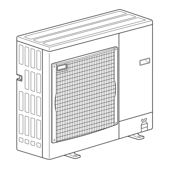
Outd oor unit
[ Mod el Names]
PU-P71VHA
PU-P71YHA
PU-P100VHA
PU-P100YHA
PU-P125YHA
PU-P140YHA
[ Serv ice Ref.]
Serv ice Ref. is on page 2.
R410A
PUH-P71VHA
PUH-P71YHA
PUH-P100VHA
PUH-P100YHA
PUH-P125YHA
PUH-P140YHA
CONTENTS
1. TECHNICAL CHANGES ................................... 2
2. REFERENCE MANUAL .................................... 4
3. SAFETY PRECAUTION ................................... 5
4. FEATURES ....................................................... 8
5. SPECIFICATIONS ............................................ 9
6. DATA .............................................................. 13
7. OUTLINES AND DIMENSIONS ..................... 17
8. WIRING DIAGRAM ........................................ 21
9. WIRING SPECIFICATIONS ........................... 26
10. REFRIGERANT SYSTEM DIAGRAM ................ 31
11. TROUBLESHOOTING ................................... 33
12. FUNCTION SETTING .................................... 74
14 EASY MAINTENANCE FUNCTION · · · · · · · · · · · · · 98
15. DISASSEMBLY PROCEDURE ..................... 105
16. PARTS LIST .................................................. 114
17. SERVICE PARTS LIST ................................. 120
J uly 2019
No.OC379
REVISED EDITION-J
Revision:
• Some descriptions have
been modified in REV ISED
EDITION-J.
OC37 9 REV ISED EDITION-H
is void.
Note:
• This manual describes ser-
vice data of the outdoor
units only.
Advertisement
Table of Contents


Need help?
Do you have a question about the PU-P71VHA 2.UK Series and is the answer not in the manual?
Questions and answers