Table of Contents
Advertisement
SPLIT-TY PE, HEAT PUMP AIR CONDITIONERS
SPLIT-TY PE, AIR CONDITIONERS
SERVICE MANUAL
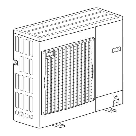
Outd oor unit
[ Mod el Names]
PU-P71VHA
PU-P71YHA
PU-P100VHA
PU-P100YHA
PU-P125YHA
PU-P140YHA
[ Serv ice Ref.]
Serv ice Ref. is on page 2.
R410A
PUH-P71VHA
PUH-P71YHA
PUH-P100VHA
PUH-P100YHA
PUH-P125YHA
PUH-P140YHA
CONTENTS
1. TECHNICAL CHANGES ................................... 2
2. REFERENCE MANUAL .................................... 4
3. SAFETY PRECAUTION ................................... 5
4. FEATURES ....................................................... 8
5. SPECIFICATIONS ............................................ 9
6. DATA .............................................................. 13
7. OUTLINES AND DIMENSIONS ..................... 17
8. WIRING DIAGRAM ........................................ 21
9. WIRING SPECIFICATIONS ........................... 26
10. REFRIGERANT SYSTEM DIAGRAM ................ 31
11. TROUBLESHOOTING ................................... 33
12. FUNCTION SETTING .................................... 74
14 EASY MAINTENANCE FUNCTION · · · · · · · · · · · · · 98
15. DISASSEMBLY PROCEDURE ..................... 105
16. PARTS LIST .................................................. 114
17. SERVICE PARTS LIST ................................. 120
J uly 2019
No.OC379
REVISED EDITION-J
Revision:
• Some descriptions have
been modified in REV ISED
EDITION-J.
OC37 9 REV ISED EDITION-H
is void.
Note:
• This manual describes ser-
vice data of the outdoor
units only.
Advertisement
Table of Contents

Related Manuals for Mitsubishi Electric PU-P71YHA 2.UK Series


Summarization of Contents
2 REFERENCE MANUAL
2-1. INDOOR UNIT’ S SERVICE MANUAL
Lists service manuals for various indoor units and their corresponding service references and manual numbers.
2-2. TECHNICAL DATA BOOK
References a technical data book with manual number OCS07.
3 SAFETY PRECAUTION
3-1. ALWAYS OBSERVE FOR SAFETY
Emphasizes disconnecting all supply circuits before accessing terminals for safety.
3-2. CAUTIONS RELATED TO NEW REFRIGERANT
Provides specific warnings and precautions for units using R410A refrigerant.
SAFETY PRECAUTION
[3] Service tools
Lists exclusive service tools recommended for R410A refrigerant usage.
[1] Cautions for service
Outlines essential service procedures like collecting refrigerant and using filter driers.
[2] Additional refrigerant charge
Details the procedure for charging refrigerant directly from a cylinder.
6 DATA
6-1. REFILLING REFRIGERANT CHARGE (R410A : kg)
Provides refrigerant charge quantities in kg for various models based on piping length.
6-2. COMPRESSOR TECHNICAL DATA
Presents technical data for compressors, including winding resistance at 20°C.
6-3. NOISE CRITERION CURVES
Displays noise level (dB) in octave bands for cooling and heating modes for different models.
6-4. STANDARD OPERATION DATA
Lists standard operation data for various unit models including electrical and refrigerant circuit parameters.
7 OUTLINES AND DIMENSIONS
1 FREE SPACE (Around the unit)
Specifies the required free space around the unit for installation and access.
2 SERVICE SPACE
Details the necessary service space dimensions for maintenance access.
3 FOUNDATION BOLTS
Provides information on securing the unit firmly with foundation bolts (M10).
4 PIPING-WIRING DIRECTIONS
Explains that piping and wiring connections can be made from four directions: front, right, rear, and below.
Piping Knockout Hole Details
Shows detailed information and dimensions for piping knockout holes, including gas and liquid pipe connections.
9 WIRING SPECIFICATIONS
9-1. FIELD ELECTRICAL WIRING (power wiring specifications)
Details wiring size, circuit rating, and power supply specifications for field electrical wiring.
Synchronized twin and triple system Electrical wiring
Illustrates electrical wiring for synchronized twin and triple systems.
WIRING SPECIFICATIONS
9-2. SEPARATE INDOOR UNIT/ OUTDOOR UNIT POWER SUPPLIES
Provides guidance on connecting indoor and outdoor units when they have separate power supplies.
WIRING SPECIFICATIONS
9-3. INDOOR – OUTDOOR CONNECTING CABLE
Specifies cable length, wire size, and polarity for indoor-outdoor connecting cables.
9 M-NET WIRING METHOD
9-4. M-NET WIRING METHOD
Details precautions and methods for M-NET wiring, including avoiding noise and proper grounding.
M-NET WIRING METHOD
9-4-1. M-NET address setting
Explains how to set M-NET addresses using rotary switches on the outdoor unit's M-NET board.
9-4-2. Refrigerant address setting
Describes how to set refrigerant addresses using DIP switches on the outdoor controller board.
9-4-3. Regulations in address settings
Outlines rules for setting M-NET and refrigerant addresses, especially for multiple grouping systems.
11 TROUBLESHOOTING
11-1. TROUBLESHOOTING
Provides a summary of actions for troubleshooting based on unit conditions and check codes.
11-2. CHECK POINT UNDER TEST RUN
Lists critical checks to perform before starting a test run and during operation.
11-3. HOW TO PROCEED " SELF-DIAGNOSIS"
Explains how to access and perform self-diagnosis functions for the air conditioner.
11-4 SELF-DIAGNOSIS ACTION TABLE
Details diagnostic codes, their meanings, cases, and recommended actions for troubleshooting.
11-5 TROUBLESHOOTING OF PROBLEMS
Lists common operational phenomena and their potential causes and countermeasures.
TROUBLESHOOTING
11-2-1. Before test run
Lists critical checks to perform before starting a test run and during operation.
11-2-2. Test run for wired remote controller
Details the procedure for performing a test run using the wired remote controller.
HOW TO PROCEED " SELF-DIAGNOSIS"
11-3-1. Self-diagnosis
Explains how to access and perform self-diagnosis functions for the air conditioner.
11-3-2. Remote controller check
Describes how to diagnose the remote controller's functionality and identify potential issues.
11-3-3. When a Problem Occurs During Operation
Details how the system displays problems during operation and how to clear check codes.
11-3-4. Self-Diagnosis During Maintenance or Service
Explains how to recall and reset check code history for each unit.
11-3-5. Remote Controller Diagnosis
Guides on diagnosing remote controller issues, including checking power and transmission errors.
11-3-6. Malfunction-diagnosis method by wireless remote controller
Outlines the procedure for diagnosing malfunctions using a wireless remote controller.
12 FUNCTION SETTING
12-1. UNIT FUNCTION SETTING BY THE REMOTE CONTROLLER
Explains how to set various unit functions using the remote controller.
12-1-1. Selecting functions using the wired remote controller
Guides on selecting functions via the wired remote controller, including password entry.
12-1-2. Selecting functions using the wired remote controller
Details the process of setting indoor unit refrigerant addresses and unit numbers.
12-1-3. Selecting functions using the wireless remote controller (Type C)
Explains how to select functions using the wireless remote controller, including mode and setting selection.
12-2. FUNCTION SELECTION OF REMOTE CONTROLLER
Provides a guide to the function buttons and LCD display for the PAR-31MAA remote controller.
12-2-1. PAR-31MAA
Provides a guide to the function buttons and LCD display for the PAR-31MAA remote controller.
13 MONITORING THE OPERATION DATA BY THE REMOTE CONTROLLER
13-1. HOW TO " MONITOR THE OPERATION DATA"
Explains how to monitor operation data like thermistor temperatures and check codes via the remote controller.
13-1-2. PAR-21MAA
Details the procedure for monitoring operation data using the PAR-21MAA remote controller.
14 EASY MAINTENANCE FUNCTION
14-1. SMOOTH MAINTENANCE
Describes the Smooth Maintenance function for checking operation data and reducing maintenance work.
14-1-1. PAR-31MAA
Details the procedure for using the Smooth Maintenance function with the PAR-31MAA controller.
14-2 REFRIGERANT LEAK CHECK (except RP170, 200)
14-2-1. PAR-31MAA
Details the procedure for performing a refrigerant leak check using the PAR-31MAA remote controller.
16 PARTS LIST ( non-RoHS compliant )
STRUCTURAL PARTS
Lists structural components of the outdoor unit, including part numbers and specifications.
FUNCTIONAL PARTS
Lists functional components of the outdoor unit, including part numbers and specifications.
17 SERVICE PARTS LIST
STRUCTURAL PARTS
Lists structural components of the outdoor unit, including part numbers and specifications.
Need help?
Do you have a question about the PU-P71YHA 2.UK Series and is the answer not in the manual?
Questions and answers