
Related Manuals for PR electronics 5115


Summary of Contents for PR electronics 5115
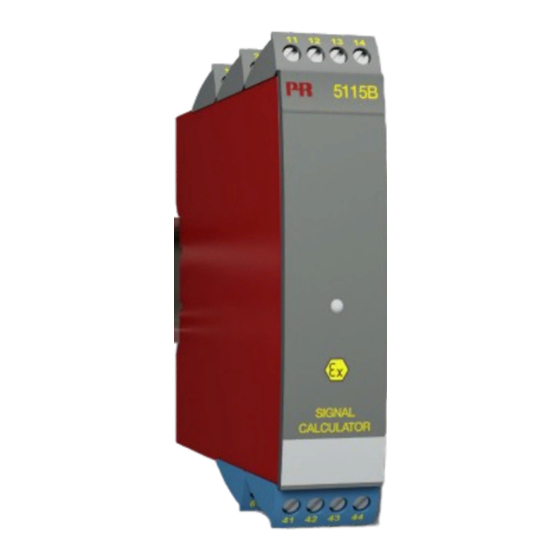
- Page 1 5 1 1 5 S i g n a l c a l c u l a t o r N r . 5 1 1 5 V 1 0 4 - U K S e r . n o . 0 0 0 3 9 5 0 0 1 - 1 9 1 1 2 9 0 0 0...
- Page 2 PR electronics A/S tilbyder et bredt program af analoge og digitale signalbehandlingsmoduler til industriel automation. Programmet består af Isolatorer, Displays, Ex-barrierer, Temperaturtransmittere, Universaltransmittere mfl. Vi har modulerne, du kan stole på i selv barske miljøer med elektrisk støj, vibrationer og temperaturudsving, og alle produkter opfylder de strengeste internationale standarder.
-
Page 3: Table Of Contents
Mounting / installation ................. Applications....................Order: 5115 ....................Electrical specifications................ Connections ....................13 Block diagram ................... 16 Selection of input type (5115A) ............17 5115 connection to Loop Link ............17 Function description ................18 5 11 5 V 1 04 - UK... -
Page 4: Warning
General mounting, connection and disconnection of wires. Troubleshooting the device. Repair of the device and replacement of circuit breakers must be done by PR electronics A/S only. WARNING SYSTEM 5000 must be mounted on DIN rail according to DIN 46277. -
Page 5: Symbol Identification
SymbOL IDENTIFICATION Triangle with an exclamation mark: Warning / demand. Potentially lethal situations. The CE mark proves the compliance of the device with the essential requirements of the directives. The double insulation symbol shows that the device is protected by double or reinforced insulation. Ex devices have been approved for use in connection with installations in explosive areas. - Page 6 LIAbILITy To the extent that the instructions in this manual are not strictly observed, the custom er cannot advance a demand against PR electronics A/S that would other- wise exist according to the concluded sales agreement. 5115V10 4 -UK...
-
Page 7: How To Demount System 5000
HOW TO DEmOUNT SySTEm 5000 First, remember to demount the connectors with hazardous voltages. Picture 1: Detach the device from the DIN rail by lifting the bottom lock. Picture 2: By lifting the upper lock and pulling the front plate simultaneously the PCB can be removed Switches and jumpers can now be adjusted. -
Page 8: Application
SIGNAL CALCULATOR PRETRANS 5115 • Redundancy measurement with 2 input signals • Signal calculator with four arithmetical operations • Duplication of the input signal • Input for RTD, Ohm, TC, mV, mA, and V • Universal AC or DC supply Application • Redundancy measurement of temperature by means of two sensors, where the... -
Page 9: Applications
APPLICATIONS Redundancy measurement Output Sensor error Supply 1 sensor 2 outputs Output 1 Output 2 Supply Arithmetical operations: A + B, A - B, 2 signals of 4...20 mA A * B, and A / B A - B Transmitter B Supply 1 signal of 4...20 mA 2 outputs... -
Page 10: Order: 5115
Order: 5115 Type Version Input 5115 Standard : A RTD / TC / mV / R / mA / V ATEX Ex : B RTD / TC / mV / R mA / V / mV Input 1, RTD / TC / mV / R... - Page 11 Accuracy, the greater of general and basic values: General values Absolute Temperature Input type accuracy coefficient ≤ ±0.05% of span ≤ ±0.01% of span / °C Basic values Basic Temperature Input type accuracy coefficient ≤ ±4 µA ≤ ±0.4 µA / °C ≤...
- Page 12 Electrical specifications - temperature input: Max. offset ..............50% of selec. max. value TC input: Min. Max. Min. Type temperature temperature span Standard +400°C +1820°C 200°C IEC584 -100°C +1000°C 50°C IEC584 -100°C +1200°C 50°C IEC584 -180°C +1372°C 50°C IEC584 -100°C +900°C 50°C DIN 43710...
- Page 13 Current input: Measurement range ..........0...100 mA Min. measurement range (span) ......4 mA Input resistance: Supplied unit.............. Nom. 10 Ω + PTC 10 Ω Non-supplied unit ............ R = ∞, V < 6 V SHUNT DROP Voltage input: Measurement range ..........0...250 VDC Min. measurement range (span) ......5 mVDC Max.
- Page 14 Terminal 31, 32 and 33 U m .................. : 250 V Ex / I.S data for 5115 b1 (input 1 for 5115 b3): Terminal 41, 42, 44 to 43 (51, 52, 54 to 53) U o ................... : 7.5 VDC I o ..................
-
Page 15: Connections
CONNECTIONS Supply: Inputs: RTD, 2-wire RTD, 3-wire RTD, 4-wire TC, internal CJC 41 42 41 42 41 42 RTD, 2-wire RTD, 3-wire RTD, 4-wire TC, internal CJC 51 52 51 52 51 52 TC, external CJC Resistance, 2-wire Resistance, 3-wire Resistance, 4-wire 41 42 41 42 41 42... - Page 16 CONNECTIONS Inputs: 2-wire transmitter Current 41 42 41 42 41 42 2-wire transmitter Current 51 52 51 52 51 52 Voltage> 2.5 V Voltage <= 2.5 V Potm. via 2.5 V ref. 41 42 41 42 41 42 Voltage > 2.5 V Voltage <= 2.5 V Potm.
- Page 17 CONNECTIONS Outputs: Current 2-wire installation Voltage Current and voltage 11 12 11 12 11 12 11 12 Current Voltage Current and voltage 2-wire installation 21 22 21 22 21 22 21 22 5 11 5 V 1 04 - UK...
-
Page 18: Block Diagram
bLOCK DIAGRAm 5115V10 4 -UK... -
Page 19: Selection Of Input Type (5115A)
JP 3 JP 4 Temperature input 1 Temperature input 2 Current / voltage input 1 Current / voltage input 2 5115 CONNECTION TO LOOP LINK C O M Loop Link Commu- nication 5115 5 11 5 V 1 04 - UK... -
Page 20: Function Description
FUNCTION DESCRIPTION In general: Output 1 and output 2 can be configured for standard current / voltage signals in the ranges 0/4...20 mA and 0...10 VDC. When selecting the arithmetical functions, up to 4 constants, K1, K2, K3, and K4, must also be defined. The functions can be selected individually for both outputs. - Page 21 Subtraction: (Input 1 * K1 - Input 2 * K2 + K4) After calculation, the result of the subtraction is transmitted to the selected out put. Input 1 must be the highest signal, or the offset constant K4 must be of sufficient value to ensure that the output is not negative.
- Page 22 Configuration of K4: In the above example, there is no offset on the output, K4 is thus set to 0. Input 1 + K1 Division: * K3 + K4 Input 2 + K2 After calculation, the result of the division is transmitted to the selected output.
- Page 23 Green LED function: The green front LED indicates the following states: Normal operation, i.e. no errors: the LED flashes quickly. Functional error: the LED lights constantly. Sensor error on input 1: the LED flashes once per second. Sensor error on input 2: the LED flashes twice per second.
- Page 24 Displays Programmable displays with wide selection of inputs and outputs for display of temperature, volume and weight, etc. Feature linearisation, scaling, and difference measurement functions for programming via PReset software. Ex interfaces Interfaces for analogue and digital signals as well as HART signals between sensors / I/P converters / ®...
- Page 25 www.prelectronics.de sales@prelectronics.de www.prelectronics.es sales@prelectronics.es www.prelectronics.it sales@prelectronics.it www.prelectronics.se sales@prelectronics.se www.prelectronics.co.uk sales@prelectronics.co.uk www.prelectronics.com sales@prelectronics.com www.prelectronics.cn sales@prelectronics.cn Head office Denmark www.prelectronics.com PR electronics A/S sales@prelectronics.dk Lerbakken 10 tel. +45 86 37 26 77 DK-8410 Rønde fax +45 86 37 30 85...
Need help?
Do you have a question about the 5115 and is the answer not in the manual?
Questions and answers