
Related Manuals for Centrometal EKO-CK P 20-40


Summary of Contents for Centrometal EKO-CK P 20-40
- Page 1 TECHNICAL INSTRUCTIONS FOR THE COMMISSIONING AND ADJUSTMENT Cm Pelet-set (14-35 kW) For boilers: EKO-CK P 20-40 (EKO-CK 20-40) EKO-CKB P 20-40 (EKO-CKB 20-40) TUPS-M-1-2017-E-N-ENG...
-
Page 2: Table Of Contents
Technical instructions for the commissioning and adjustment CONTENTS 1. Introduction ...…………………………………………………………………………………………….. 2. Status at delivery ………………………………………………………………………………………… 3. Technical data …………………………………………………………………………………………… 4. Installation of Cm Pelet-set ..………………………………………………………………..………….. 4.1. Installation of pellet burner and pellet control unit on boiler ..……………..…………... 4.2. Installation of pellet tank CPSP and pellet feeder CPPT …..………………………..….. 5. -
Page 3: Introduction
Technical instructions for the commissioning and adjustment 1. Introduction Cm Pelet-set, pellet based heating system (nominal burner output of 14 kW and from 20 to 35 kW) designed for installation in combined boilers or biomass firing boilers EKO-CK P (EKO-CK) and EKO- CKB P (EKO-CKB), with thermal output from 20 to 40 kW. -
Page 4: Installation Of Cm Pelet-Set
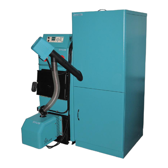
Technical instructions for the commissioning and adjustment Cm Pelet-set on boilers EKO-CK P (EKO-CK) and EKO-CKB P (EKO-CKB) Cm Pelet-set type Burner CPPL type CPPL-14 CPPL-35 CPPL-35 CPPL-35 CPPL-35 Set thermal output (kW) EKO-CK EKO-CK EKO-CK EKO-CK EKO-CK P/CKB P 25 P/CKB P 30 P/CKB P 35 P/CKB P 40... - Page 5 Technical instructions for the commissioning and adjustment feeding box and tighten the screws with enclosed nuts M8. Put a gasket onto the feeding box and put a feeding tube onto it (faced toward the pellet tank, either on the left or on the right side and tighten it firmly using enclosed screws M4 x 15.
- Page 6 Technical instructions for the commissioning and adjustment d) Set the micro switch (1) in lower left or right corner (depend about opening direction of lower boiler door) of the lower front casing of the boiler (3) using 2 screws, put the cover (2) according to the picture on micro switch and fasten it with the screw.
- Page 7 Technical instructions for the commissioning and adjustment e) Assembly the pellet tank CPSP according to technical instructions and position it next to the right or left boiler side onto horizontal surface. Align tank bottom with the boiler bottom and align the front tank side with the front side of boiler plating.
- Page 8 Technical instructions for the commissioning and adjustment Figure 1a. Connection scheme of the boiler EKO-CK P / EKO-CKB P (EKO-CK / EKO-CKB) with in-built Cm Pelet-set on heating installation with stainless steel hot water boiler: 1. Boiler EKO-CK P / EKO-CKB P (EKO-CK / EKO-CKB) with in-built Cm Pelet-set 2.
-
Page 9: Installation Of Pellet Tank Cpsp And Pellet Feeder Cppt
Technical instructions for the commissioning and adjustment 4.2. Installation of CPSP pellet tank and CPPT pellet feeder See Technical instructions for installation, use and maintenance of pellet tank and feeder supplied with CPSP pellet tank and CPPT screw feeder. 5. Draught of the chimney Chimney of appropriate size is one of conditions for proper operation of the boiler. -
Page 10: Symbol Description
Technical instructions for the commissioning and adjustment Manual switch on of the pellet feeder. It is used to supply the feeder with pellets (after tank cleaning, tank discharge…). 6.2. Symbol description Indication of operation of the sanitary water heating pump Indication of operation of the heating pump circuit. -
Page 11: The Basic Software Configuration
Technical instructions for the commissioning and adjustment 6.4. The basic software configuration (by authorized service) It is used for the case: - on CentroPlus/-B boiler firing with solid fuel / pelets: adjusting the temperature of the boiler for the first firing a pellet burner (for CentroPlus /-B boilers fired with solid fuel / wood pellets) when working on wood without accumulation tank (CAS) - adjust the maximum temperature in the accumulation tank (CAS) for the first firing a pellet burner (if accumulation tank (CAS) is installed). - Page 12 Technical instructions for the commissioning and adjustment temperature setting). If "OP02" is turned on then domestic hot water sensor is defined as a accumulation tank sensor it is necessary to set at the lowest sensor sleeve on the last accumulation tank (CAS) or in sensor sleeve below the level that we want to heat up in accumulation tank (CAS).
- Page 13 Technical instructions for the commissioning and adjustment OP07 - Work with external controller or remote control "telecontrol" Factory setting: "0" (turned off) Available setting: "0" (turned off), "1" (turned on). "OP07" can be turned on ("1") if "OP01" and "OP02" is turned off.
-
Page 14: Fine Tuning Of Operating Parameters Of The Burner
Technical instructions for the commissioning and adjustment 0 = burner will be start when boiler temperature drop for difference below adjusted boiler temperature (demand from room thermostat or dislocated DHW tank is not followed) Is OBLIGATORY to use on boilers with inbuilt DHW tanks (EKO-CKB P (EKO-CKB)) and POSSIBLE to use on boilers without inbuilt DHW tanks (EKO-CK P (EKO-CK)) where is wanted boiler temperature... - Page 15 Technical instructions for the commissioning and adjustment Service menu Pr08 Depending on the burner operation phase or stand-by phase (OFF mode), the following is displayed in displays after PIN is entered: Burner is not operating (''OFF'' mode): Parameter FP01 is displayed in the upper display, and set value of the parameter is displayed in the lower display Burner is operation (''ON'' mode): Current burner parameter is displayed and set value of the parameter...
- Page 16 Technical instructions for the commissioning and adjustment Overview of the burner current mode (only in transition phase) While the burner is operating, if ''-'' and ''+'' buttons are pressed simultaneously, transition phase (PPX) is displayed in the lower display and total time of the transition phase remaining to transition to the next phase is counted down in the upper display.
- Page 17 Technical instructions for the commissioning and adjustment FP06 Working time of electric heater after photocell 60 sec. 0 - 99 sec. has detected flame FP07 Initial fire developing time from flame 120 sec 0 - 999sec. occurrence to transition to P1 FP08 Not used FP09...
- Page 18 Technical instructions for the commissioning and adjustment If value of any parameter is changed from its factory setting, the modified parameter is blinking to enable the fitter/serviceman to notice such change. CPPL-35 TABLE WITH FINE TUNING OF BURNER OPERATING PARAMETERS Param.
- Page 19 Technical instructions for the commissioning and adjustment programme P4 0 – 999 sec. FP36 Burner work time in transition phase in 75 sec. programme P5 FP37* Suction system configuration 2- suction system is not installed 3- suction system is installed 1 –...
-
Page 20: Burner Operation Modes
Technical instructions for the commissioning and adjustment 6.6. Burner operating mode The burner operation in each mode (current mode can be seen on displays of the control unit) is described below: Mode A0: Fan is operating at max. speed and after expiry time FP3 it goes to Mode A1. If '-' is pressed, A0 Mode is displayed in the lower display and time to FP3 is counted down in the upper display. - Page 21 Technical instructions for the commissioning and adjustment Mode PP1: Fan works at FP12 speed. Screw alternately turns on (FP13) and turns off (FP14) until FP32 time expires and then goes to Mode PP2. If output of P2 on control unit is set, it goes to Mode A6. If '-' is pressed, PP1 Mode is displayed in the lower display and time to FP13 or FP14 is counted down in the upper display.
- Page 22 Technical instructions for the commissioning and adjustment If '-' and 'SET' are pressed, „FP:19“ or „FP:20“, is displayed in the lower display, and FP19 or FP20 parameter value is displayed in the upper display. If '-' and '+' are pressed, PP4 Mode is displayed in the lower display and time to FP35 is counted down in the upper display.
- Page 23 Technical instructions for the commissioning and adjustment Sub-Mode 3: Counting down of 2 minutes starts. If temperature T is reached within this time, it goes to Mode A7 (extinction). If time of 2 minutes expires, it increases output by two stages (on P4) and goes to sub-Mode 5 Sub-Mode 4: If temperature T -2 is reached, it sets output to two stages less than set (on P4) and goes to sub-...
-
Page 24: Interruption Of Power Supply
Technical instructions for the commissioning and adjustment Mode A7 Screw is turned off. Sub-Mode 1: Fan operates at speed at which it was operating in previous Mode. Counting down of time FP9 starts. If this time expires or flame extinguishes (10s+5s) before time expires, it goes to sub-Mode 2. Sub-Mode 2: Fan operates at maximum speed until FP10 time expires and then goes to sub-Mode 3. - Page 25 Technical instructions for the commissioning and adjustment...
- Page 26 Technical instructions for the commissioning and adjustment...
- Page 27 Technical instructions for the commissioning and adjustment...
-
Page 28: The Possibility Of Fan Lid Installing
Built-in fan lid - elements that are built into the burner (under the protective box) Centrometal d.o.o. shall not be responsible for possible incorrect data caused by printing errors or errors during transcription and in any case, it reserves the right to modify its products deemed to be required and useful, without any prior notification...
Need help?
Do you have a question about the EKO-CK P 20-40 and is the answer not in the manual?
Questions and answers