Table of Contents
Advertisement
Quick Links
Advertisement
Table of Contents

Related Manuals for Centrometal EKO-CKS P 140


Summary of Contents for Centrometal EKO-CKS P 140
- Page 1 HEATING TECHNIQUE Centrometal d.o.o. - Glavna 12, 40306 Macinec, Croatia, tel: 040 372 600, fax: 040 372 611 TECHNICAL INSTRUCTIONS for installation, use and maintenance of hot water boiler and installation of additional equipment EKO-CKS P UNIT TU-CKSP-10-2022-ENG...
-
Page 2: Technical Data
TECHNICAL DATA EKO-CKS P UNIT Boiler body EKO-CKS P 150 EKO-CKS P 200 EKO-CKS P 250 EKO-CKS P 300 EKO-CKS P 380 EKO-CKS P 500 EKO-CKS P 550 EKO-CKS P 600 Cm Pelet set Burner CPPL-200 inv CPPL-200 inv CPPL-300 inv CPPL-300 inv CPPL-350 inv CPPL-600 inv... - Page 3 Pellet tank on the left side of the boiler (standard delivery state) CI*** SPLV CI*** AE*** ACK*** Delivery state only by order: * Installation of pellet tank on the right side of the boiler ** Installation two boilers on the one pellet tank AC*** *** Additional equipment CI***...
- Page 4 COMPONENTS EKO-CKS P UNIT (140-560 kW) Additional equipment involved Basic equipment (OO) into the configurations Obligatory equipment Power Boiler AC-K AC+K Cm Pelet-set range (kW) EKO-CKS P EKO-CKS P Cm Pelet-set 200: 42 - 140 - Electrical enclosure with UNIT 140 - pellet burner CPPL-200 inv - pellet controller and control unit...
- Page 5 IMPORTANT: Connection of the boiler to the chimney and to the central heating system as well as the start-up has to be performed by the authorized person licensed on behalf of Centrometal d.o.o. company. 1.1. CM PELET SET DESCRIPTION 1.1.1.
- Page 6 TECHNICAL DATA AND DIMENSIONS OF CPPL BURNERS POWER [kW] ELECTRIC HEATER FEEDER SCREW FAN [W] MODEL POWER SUPPLY MIN. MAX. CPPL-200 inv 230V, 50 Hz CPPL-300 inv 230V, 50 Hz CPPL-350 inv 230V, 50 Hz CPPL-600 inv 230V, 50 Hz DIMENSIONS: CPPL-200 inv, CPPL-300 inv, CPPL-350 inv MODEL...
- Page 7 CPPL-600 inv c t i Technical instructions EKO-CKS P UNIT...
- Page 8 1.1.2. FEEDER SCREW DESCRIPTION The pellets feed system is granted by a screw and it is composed by: - Motor device with gearbox, with an high starting torque - Cable with electrical connection with the connector - Steel spiral - Motor device support with gearbox - Steel pipes - Flexible pipes for connection of the screw/burner - Clamping bands...
-
Page 9: Delivery State
- pellet tank (CentroPelet Box) or feeding conveyor for pellet supply from the seasonal tank into the pellet burner according to the Centrometal’s recommendation - the boiler return flow protection by a 3-way mixing valve with actuator and boiler pump... -
Page 10: Fuel Characteristics
3.0. FUEL Hot water boiler EKO-CKS P UNIT can be fired with wood pellets (C1 by EN 303-5:2012; A1 by ISO 17225-2:2014). FUEL CHARACTERISTICS - heating value: >= 5 kWh/kg (18 MJ/kg) - diameter: <= 6 mm - max. moisture content: <= 12 % - max. - Page 11 4.2. MINIMAL DISTANCES FROM THE BOILER ROOM WALLS Minimal distances from the boiler room walls for the boiler EKO-CKS P UNIT and pellet tank Centropelet box 2700 140-180 1000 1000 1000 1000 1200 1200 1200 1150 Flammable items must not be placed on the boiler and within the safety distances.
- Page 12 4.3. OPENING FOR FRESH AIR Each boiler room must be equipped with opening for supply of fresh air which is dimensioned in accordance with boiler output. Such opening must be protected with a net or grate. The boiler location must never be under negative pressure. A - opening area in cm Equation for calculate opening area: A = 6,02 Q...
- Page 13 5.0. SAFETY THERMOSTAT INSTALLATION With boiler is delivered PVC box which consist safety thermostat. PVC box (marked with „X2") must be installed when are casing cover mounted on boiler. Place PVC box on upper casing cover side (A) and fix it with four screws through factory prepared holes. Place boiler sensor and safety thermostat sensor on common sensors tube which is placed below front casing cover (B).
- Page 14 5.1. INSTALL PELLET BURNER CPPL TO LOWER BOILER DOOR Parts needed for the burner installation are shown in Figure 1. The burner shall be fixed with 6 screws M10x20 mm onto the extension flange which is installed on the lower boiler door. The presostat (pressure switch) tube (3) is on one side fixed to the presostat on the burner CPPL (2), and in the other side there is shallow pin (4) to connect the tube to the boiler door.
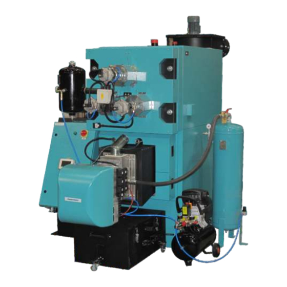
- Page 15 Figure 2. Install equipment Detail A Detail A Pellet tank (CentroPelet box 2,7 m or similar) Pressure vessel: 50l for CPPL 200,300,350 inv 2 x 50l for CPPL 600 inv Junction box with boiler control unit and touchscreen display Tube for connecting air compressor and pressure vessel Boiler EKO-CKS P Air compressor...
- Page 16 ROTARY DOSING VALVE INSTALLATION (RSE) (ADDITIONAL EQUIPMENT) Prior to any work on the boiler, the el. power must be switched OFF on the device to disconnect all poles of the power supply. ROTARY DOSING VALVE AS ADDITIONAL EQUIPMENT MUST BE ORDER WHEN ORDERING A BOILER, BECAUSE TO ADJUST THE ELECTRIC CABINET.
- Page 17 After the rotary valve is properly attached to the burner, it is necessary to connect it to the electrical cabinet in the intended place on the terminal block. An electrical wiring diagram is supplied with the boiler, indicating the connection point for the rotary valve (symbol x24). Then it is necessary to turn on the rotary valve (Dispenser) in the boiler control under the PIN for the installer and check the correctness of the operation using a manual test.
-
Page 18: Connection To The Chimney
6.0. CONNECTION TO THE CHIMNEY Properly dimensioned and built chimney is the main condition for safe and economical functioning of the boiler. The thermal insulation of the chimney has to be done properly, it has to be absolutely gas-proof and smooth. On its lower part there has to be built in the opening for cleaning with the door. -
Page 19: Filling The System
7.0. BOILER INSTALLATION TO CENTRAL HEATING SYSTEM All installation works must be made in accordance with valid national and European standards. Boiler EKO-CKS P UNIT can be connected to closed or open central heating systems. Boiler can be fired with wood chip and wood pellets. Installation should be made, in according to technical standards, by a professional who will be responsible for proper boiler operation. - Page 20 7.2. BOILER INSTALLATION TO CLOSED HEATING SYSTEM In closed heating system (as in example shown in Figure 3.) it is obligatory to build in certified safety valve with opening pressure of max. 3 bar and a closed expansion vessel. Safety valve and expansion vessel must be built in accordance with professional rules and any valve must not be located between safety valve and expansion vessel and boiler.
- Page 21 7.3. BOILER INSTALLATION TO OPEN HEATING SYSTEM 7.3.1. INSTALLATION TO OPEN EXPANSION VESSEL The boiler has to be connected to the open system according to the Figure 4. All connections from the boiler to the open expansion vessel and from the open expansion vessel to the boiler have obligatory to be covered by the thermal insulation of min.
- Page 22 Figure 5. General connection scheme of the EKO-CKS P UNIT to te open heating system LEGEND: F - Thermal insulation of the safety boiler A - Boiler flow output B - Boiler return G - Automatic air vent pot C - Safety line - Safety inlet line - accord.
-
Page 23: Boiler Startup
8.0. BOILER STARTUP Boiler commisioning must be performed by the authorized service man of the company Centrometal d.o.o. who will be commission boiler and additional equipment by Commissioning list, carry out training of boilerman or responsible person for using boiler and make report about training with trained person signature. - Page 24 BOILER START (TURN ON): For boiler start is neccesary to press ON / OFF button. After pressing ON / OFF button on display will be displayed window for boiler start confirmation. Press „OK” to confirm boiler start. Operation S TA R T? Info BOILER STOP (TURN OFF): For boiler stop is neccesary to press ON / OFF button.
-
Page 25: Cleaning And Maintenance
10.0. CLEANING AND MAINTENANCE Cleaning intervals depend about quality of used wood pellets - worse pellets quality - more often cleaning. Cleaning intervals depend about installed additional equipment. ITEM DESCRIPTION CLEANING INTERVAL Pellet burner Every 300 working hours or as Clean accumulated ash from burner grate. - Page 26 10.1. PELLET BURNER CLEANING Clean ash / sediments on burner grate, clean space below grate. Cleaning procedure: 1) remove flexible connection tube from pellet burner (remove clamp) 2) remove upper and lower casing cover from lower boiler door 3) unscrew two nuts and open lower boiler door with burner 4) remove burner extension and take out burner grate 5) clean burner grate and space below burner grate 6) restore everything to original state...
- Page 27 10.3. FLUE GAS TUBES CLEANING (without automatic cleaning) Take out turbulators from tubes of 1st and 2nd passage, clean tubes, put back turbulators in tubes. Cleaning procedure: 1) remove flexible connection tube from pellet burner (remove clamp) 2) remove upper sides casing cover from upper boiler door 3) unscrew two nuts and open upper boiler door 4) take out turbulator from all tubes 5) use cleaning brush and clean all tubes through all lenghtwise...
- Page 28 10.5. FLUE GAS CHAMBER CLEANING Remove lids from flue gas chamber and clean flue gas chamber by using scraper. Cleaning procedure: 1) remove lids from opening fro cleaning of flue gas chamber 2) use scraper and clean ash from flue gas chamber 3) restore everything to original state 10.6.
- Page 29 10.7. ASH EXTRACTION (with automatic sistem for ash extraction) Empty ash box(es). Cleaning procedure: 1) relase ash box(es) holders 2) pull out ash box 3) empty ash box(es) 4) restore everything to original state 10.8. CYCLONE ASH BOX CLEANING Empty cyclone ash box. Cleaning procedure: 1) relase cyclone ash box holders 2) pull out cyclone ash box...
- Page 30 10.9. CHECKING FLEXIBLE CONNECTION TUBE Check and, if si needed, adjust flexible connection tube straight to burner for smooth pellet drop to burner. Procedure: 1) if flexible tube is not straight relase clamps, realign flexible tube and fasten clamps. 10.10. FEEDER SCREW AND PELLET TANK CLEANING Empty feeder screw and clean it;...
- Page 31 10.11. ELECTRIC HEATER REPLACMENT IMPORTANT! When replacing electric heater it’s neccessary to take care about correct placement of electric heater. Electric heater must be placed that electric heater can seal opening on burner head in which are placed. Otherwise, electric heate can blown out. Electric heater cane don’t seal opening Electric heater cane seal opening in burner in burner head...
- Page 32 Technical instructions PelTec-Compact Technical instructions EKO-CKS P UNIT...
- Page 33 c t i Technical instructions EKO-CKS P UNIT...
- Page 34 To the end DOWN DOWN Technical instructions PelTec-Compact Technical instructions EKO-CKS P UNIT...
- Page 35 c t i Technical instructions EKO-CKS P UNIT...
- Page 36 11.0. ELECTRICAL CONNECTIONS 11.1. BOILER SENSORS BOILER SENSORS AT STANDARD DELIVERY BUFFER TANK „CAS” HYDRAULIC CROSSOVER (if is installed) (if is installed) 1 - boiler temperature sensor, Type: NTC 5k - safety thermostat STB 2 - Flue gas temperature sensor, Type: PT1000 3 - Boiler return sensor, Type: NTC 5k 4 - Backfilling sensor 5 - Junction box temperature sensor, Type: NTC 5k...
- Page 37 ELECTRICAL SCHEMES ELECTRICAL SCHEMES ARE DELIVERED IN BOILER ELECTRIC BOX RESISTANCE LIST Pt1000 SENSOR RESISTANCE LIST NTC 5k/25°C SENSOR (measuring field -30 - +400 °C) (measuring field from -20 - +130 °C) Temperature Resis. Resis. Resis. Temperature Temperature (°C) (°C) (°C) ( W ) ( W )
- Page 38 Technical instructions PelTec-Compact Technical instructions EKO-CKS P UNIT...
- Page 39 c t i Technical instructions EKO-CKS P UNIT...
- Page 40 Centrometal d.o.o. assumes no responsibility for possible inaccuracies in this book originated typographical errors or rewriting, all the pictures and diagrams are principal and it is necessary to adjust each actual situation on the field, in any case the company reserves the right to enter their own products such modifications as considered necessary.
Need help?
Do you have a question about the EKO-CKS P 140 and is the answer not in the manual?
Questions and answers