Chapters
Table of Contents

Related Manuals for ICS Schneider Messtechnik GDM-100


Summary of Contents for ICS Schneider Messtechnik GDM-100
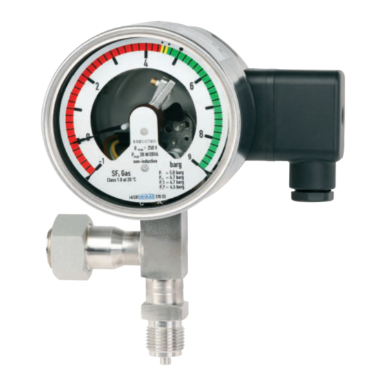
- Page 1 Gas density monitor, model GDM-100 Gasdichtewächter, Typ GDM-100 Densimètre pour gaz, type GDM-100 Densímetro, modelo GDM-100 Gas density monitor with optional recalibration valve...
- Page 2 Lire le mode d‘emploi avant de commencer toute opération ! A conserver pour une utilisation ultérieure ! ¡Leer el manual de instrucciones antes de comenzar cualquier trabajo! ¡Guardar el manual para una eventual consulta! WIKA operating instructions gas density monitor model GDM-100...
-
Page 3: Table Of Contents
1. General information 2. Design and function 3. Safety 4. Transport, packaging and storage 5. Commissioning, operation 6. Faults 7. Maintenance, cleaning and recalibration 8. Dismounting, return and disposal 9. Specifications 10. Accessories WIKA operating instructions gas density monitor model GDM-100... -
Page 4: General Information En
1. General information 1. General information ■ The instrument described in the operating instructions has been designed and manufactured using state-of-the-art technology. All components are subject to stringent quality and environmental criteria during production. Our management systems are certified to ISO 9001 and ISO 14001. ■... -
Page 5: Design And Function
Switching functions are: Normally closed, normally open, change-over contact. The magnetic snap-action contacts are control switches which open or close connected electric circuits via a contact arm which is moved by the instrument pointer. WIKA operating instructions gas density monitor model GDM-100... -
Page 6: Safety
2. Design and function / 3. Safety Optional recalibration valve With regard to switchgear safety, asset protection and environmental protection, it is common to perform functional checks of the measuring instruments on a regular basis. Article 5 of EU regulation No. 517/2014 on fluorinated greenhouse gases, provides for checking of the leakage detection system at least every 6 years if it contains more than 22 kg SF₆... - Page 7 Wherever the gas density of SF₆ gas has to be indicated locally and, at the same time, circuits need to be switched, the model GDM-100 gas density monitor finds its use. Gas density monitors are modified contact pressure gauges, specially developed for the use of SF₆...
- Page 8 3. Safety 3.3 Improper use WARNING! Injuries through improper use Improper use of the instrument can lead to hazardous situations and injuries. ▶ Refrain from unauthorised modifications to the instrument. ▶ Do not use the instrument within hazardous areas. Any use beyond or different to the intended use is considered as improper use. 3.4 Responsibility of the operator The instrument is used in the industrial sector.
- Page 9 ■ Chemically neutral ■ Inert ■ Not flammable ■ Heavier than air ■ No toxicity ■ No damage to the ozone layer Detailed information is given in IEC 60376 and IEC 61634. WIKA operating instructions gas density monitor model GDM-100...
- Page 10 3. Safety Danger of suffocation caused by insulating gases and gas mixtures High concentrations of gases can lead to asphyxiation, since breathable air is displaced from the lungs with the inhalation of gas. Since SF₆ gas is heavier than air, it collects, especially, at ground level or lower-lying rooms below the reference level (e.g.
-
Page 11: Transport, Packaging And Storage
When unloading packed goods upon delivery as well as during internal transport, proceed carefully and observe the symbols on the packaging. ▶ With internal transport, observe the instructions in chapter 4.2 “Packaging and storage”. WIKA operating instructions gas density monitor model GDM-100... -
Page 12: Commissioning, Operation
4. Transport, packaging ... / 5. Commissioning, operation 4.2 Packaging and storage Do not remove packaging until just before mounting. Keep the packaging as it will provide optimum protection during transport (e.g. change in installation site, sending for repair). WARNING! Physical injuries and damage to property and the environment caused by hazardous decomposition products Before storing the instrument, any residual decomposition products must... - Page 13 Tighten the threaded connection and check that the sealing is correctly seated, in order to ensure the ingress protection. ■ Connection details and switching functions are given on the product label. Connection terminals and ground terminal are appropriately marked. WIKA operating instructions gas density monitor model GDM-100...
- Page 14 5. Commissioning, operation 5.2.1 Limit values for the contact load with resistive load Gas-filled instruments Liquid-filled instruments Maximum rated operating AC 250 V AC 250 V voltage U Rated operating current Switch-on current Switch-off current Continuous current 0.6 A 0.6 A Maximum switching power 30 W, 50 VA 20 W, 20 VA...
- Page 15 RC element Load Capacitive load With capacitive loads elevated switch-on currents arise. These can be reduced by series-connecting resistors in the supply line. Examples: Contact protection measure with current-limiting resistor Load Load WIKA operating instructions gas density monitor model GDM-100...
-
Page 16: Faults
5. Commissioning, operation / 6. Faults 5.3 Switch point setting The switch points have a fixed setting as standard and cannot be adjusted. Thus, an undesired adjustment of the switch points is excluded. With customer-specific, adjustable switch points, with the accompanying adjustment key, the desired set point can be set via the adjustment lock in the window. -
Page 17: Maintenance, Cleaning And Recalibration
1. Before cleaning, correctly disconnect the instrument from the pressure supply and switch off the current. 2. Use the requisite protective equipment. 3. Clean the instrument with a moist cloth. Electrical connections must not come into contact with moisture! WIKA operating instructions gas density monitor model GDM-100... - Page 18 7. Maintenance, cleaning and recalibration CAUTION! Damage to the instrument Improper cleaning may lead to damage to the instrument! ▶ Do not use any aggressive cleaning agents. ▶ Do not use any hard or pointed objects for cleaning. 4. Wash or clean the dismounted instrument, in order to protect people and the environment from exposure to residual decomposition products.
-
Page 19: Dismounting, Return And Disposal
Place shock-absorbent material evenly on all sides of the transport packaging. 2. If possible, place a bag containing a desiccant inside the packaging. Information on returns can be found under the heading “Service” on our local website. WIKA operating instructions gas density monitor model GDM-100... -
Page 20: Specifications
8. Dismounting, return ... / 9. Specifications 8.3 Disposal Incorrect disposal can put the environment at risk. Dispose of instrument components and packaging materials in an environmentally compatible way and in accordance with the country-specific waste disposal regulations. 9. Specifications Specifications Nominal size Calibration pressure P... - Page 21 DIN EN ISO 15614-1 and DIN EN ISO 15614-12 by the notified body TÜV Süd Tightening torque test 40 Nm ±10 % connection Leakage rate ≤ 1 · 10 mbar · l/s Gas-tight For further specifications, see the order documentation. WIKA operating instructions gas density monitor model GDM-100...
- Page 22 9. Specifications Dimensions in mm Version without recalibration valve...
- Page 23 Version with calibration valve Any arrangement of the test valve possible Other process connections on request approx. 88 approx. 94 approx. 57 incl. protective cap approx. 88 approx. 94 approx. 57 incl. protective cap WIKA operating instructions gas density monitor model GDM-100...
-
Page 24: Accessories
10. Accessories 10. Accessories Description Order number Recalibration valve for retrofitting to gas density See WIKA data sheet monitors and other leakage detection systems SP 61.16 already installed in the field, model GLTC-CV Any arrangement of the test valve possible Other process connections on request Adapter from test connection (M26 x 1.5) to quick 14146937... - Page 25 Inhalt Inhalt 1. Allgemeines 2. Aufbau und Funktion 3. Sicherheit 4. Transport, Verpackung und Lagerung 5. Inbetriebnahme, Betrieb 6. Störungen 7. Wartung, Reinigung und Rekalibrierung 8. Demontage, Rücksendung und Entsorgung 9. Technische Daten 10. Zubehör...
-
Page 26: Allgemeines
1. Allgemeines 1. Allgemeines ■ Das in der Betriebsanleitung beschriebene Gerät wird nach dem aktuellen Stand der Technik konstruiert und gefertigt. Alle Komponenten unterliegen während der Fertigung strengen Qualitäts- und Umweltkriterien. Unsere Managementsysteme sind nach ISO 9001 und ISO 14001 zertifiziert. ■... -
Page 27: Aufbau Und Funktion
2. Aufbau und Funktion 2. Aufbau und Funktion 2.1 Überblick Gasdichtewächter Gasdichtewächter mit optionalem Rekalibrierventil Typenschild Typenschild Elektrische Anschluss, Kabeldose Elektrische Anschluss, Kabeldose Prozessanschluss, Schlüsselfläche Prozessanschluss (Gasraum) ... -
Page 28: Sicherheit De
2. Aufbau und Funktion / 3. Sicherheit Optionales Rekalibrierventil In Bezug auf Schaltanlagensicherheit, Objektschutz und Umweltschutz ist es üblich, eine regelmäßige Funktionsprüfung der Messgeräte durchzuführen. Artikel 5 der EU-Verordnung Nr. 517/2014 über fluorierte Treibhausgase sieht eine Kontrolle des Leckage-Erkennungssystems rechtlich verpflichtend mindestens alle 6 Jahre vor, falls mehr als 22 kg SF₆-Gas enthalten sind und die Anlage nach dem 1. - Page 29 Überall dort, wo die Gasdichte von SF₆-Gas vor Ort angezeigt werden muss und gleichzeitig Stromkreise geschaltet werden sollen, findet der Gasdichtewächter Typ GDM-100 seinen Einsatz. Gasdichtewächter sind abgewandelte Kontaktmanometer, die speziell für die Verwendung von SF₆-Gas entwickelt wurden. Temperatureinflüsse die auf das eingeschlossene SF₆-Gas wirken, werden durch ein Kompensationssystem ausgeglichen.
- Page 30 3. Sicherheit 3.3 Fehlgebrauch WARNUNG! Verletzungen durch Fehlgebrauch Fehlgebrauch des Gerätes kann zu gefährlichen Situationen und Verletzungen führen. ▶ Eigenmächtige Umbauten am Gerät unterlassen. ▶ Gerät nicht in explosionsgefährdeten Bereichen einsetzen. Jede über die bestimmungsgemäße Verwendung hinausgehende oder andersartige Benutzung gilt als Fehlgebrauch. 3.4 Verantwortung des Betreibers Das Gerät wird im gewerblichen Bereich eingesetzt.
- Page 31 3. Sicherheit Speziell beim Einsatz von SF₆-Gas Der Betreiber muss sicherstellen, dass die Handhabung von SF -Gas durch ein hierzu qualifiziertes Unternehmen oder von gemäß IEC 61634 Abschnitt 4.3.1 bzw. IEC 60480 Abschnitt 10.3.1 geschulten Mitarbeitern durchgeführt wird. 3.6 Persönliche Schutzausrüstung Die persönliche Schutzausrüstung dient dazu, das Fachpersonal gegen Gefahren zu schützen, die dessen Sicherheit oder Gesundheit bei der Arbeit beeinträchtigen könnten.
- Page 32 3. Sicherheit Da SF₆-Gas schwerer ist als Luft, sammelt es sich insbesondere in Bodennähe oder tiefer gelegenen Räumen unterhalb des Bezugsniveaus an (z. B. Kellerräume). Dies ist besonders gefährlich, da SF6-Gas farb- und geruchlos ist und somit vom Menschen nicht wahrgenommen wird. 3.8 Gefährdung duch Zersetzungsprodukte Isoliergas in elektrischen Anlagen kann durch Lichtbogeneinwirkung Zersetzungsprodukte enthalten:...
-
Page 33: Transport, Verpackung Und Lagerung
3. Sicherheit / 4. Transport, Verpackung und Lagerung 3.10 Beschilderung, Sicherheitskennzeichnungen Typenschild (Beispiel) Dichtewächter mit Kontakteinrichtung Density monitor with alarm contacts Schaltzustand bei Skalenanfangswert / Status of switch at minimum scale value ... -
Page 34: Inbetriebnahme, Betrieb
4. Transport, Verpackung ... / 5. Inbetriebnahme, Betrieb 4.2 Verpackung und Lagerung Verpackung erst unmittelbar vor der Montage entfernen. Die Verpackung aufbewahren, denn diese bietet bei einem Transport einen optimalen Schutz (z. B. wechselnder Einbauort, Reparatursendung). WARNUNG! Körperverletzungen, Sach- und Umweltschäden durch gefährliche Zersetzungsprodukte Vor der Einlagerung müssen alle anhaftenden Zersetzungsprodukte entfernt werden. - Page 35 5. Inbetriebnahme, Betrieb 5.1.2 Installation ■ Beim Transport oder der Lagerung kann es vorkommen, dass sich Gasdichtewächter erwärmen oder abkühlen und dies in Zeigerbewegungen resultiert. Diese Zeigerbewegungen werden durch das Kompensationssystem hervorgerufen. Um sicherzustellen, dass sich die Geräte ausreichend der Umgebungstemperatur angepasst haben, müssen sie min.
- Page 36 5. Inbetriebnahme, Betrieb 5.2.1 Grenzwerte für die Kontaktbelastung bei ohmscher Belastung Gasgefüllte Geräte Flüssigkeitsgefüllte Geräte Maximale AC 250 V AC 250 V Nennbetriebsspannung U Nennbetriebsstrom Einschaltstrom Ausschaltstrom Dauerstrom 0,6 A 0,6 A Maximale Schaltleistung 30 W, 50 VA 20 W, 20 VA Die Grenzwerte nicht überschreiten.
- Page 37 5. Inbetriebnahme, Betrieb Induktive Last bei Gleichspannung Bei Gleichspannung kann der Kontaktschutz durch eine parallel zur Last geschalteten Freilaufdiode erzielt werden. Die Polung der Diode muss so erfolgen, dass sie bei angelegter Betriebsspannung sperrt. Beispiel: Kontaktschutzmaßnahme Kontakt mit Freilaufdiode Diode Last Induktive Last bei Wechselspannung Bei Wechselspannung gibt es zwei mögliche Schutzmaßnahmen:...
-
Page 38: Störungen
5. Inbetriebnahme, Betrieb / 6. Störungen 5.3 Schaltpunkteinstellung Die Schaltpunkte sind standardmäßig fest eingestellt und können nicht verstellt werden. Dadurch ist ein ungewolltes Verstellen der Schaltpunkte ausgeschlossen. Bei kundenspezifischen verstellbaren Schaltpunkten, lässt sich mittels mitgelieferten Verstellschlüssels der gewünschte Sollwert über das Verstellschloss in der Sichtscheibe einstellen. -
Page 39: Wartung, Reinigung Und Rekalibrierung
6. Störungen / 7. Wartung, Reinigung und Rekalibrierung Störungen Ursachen Maßnahmen Schaltzustand bleibt Kontakte defekt (z. B. Gerät austauschen. Vor erneuter trotz Erreichen des Kontaktzone verschmolzen) Inbetriebnahme des neuen Schaltpunktes/ Gerätes Schutzbeschaltung für Rückschaltpunktes den Kontakt vorsehen unverändert Keine Zeigerbewegung Messwerk blockiert Gerät austauschen trotz Druckänderung... - Page 40 7. Wartung, Reinigung und Rekalibrierung VORSICHT! Beschädigung des Gerätes Eine unsachgemäße Reinigung führt zur Beschädigung des Gerätes! ▶ Keine aggressiven Reinigungsmittel verwenden. ▶ Keine harten und spitzen Gegenstände zur Reinigung verwenden. 4. Ausgebautes Gerät spülen bzw. säubern, um Personen und Umwelt vor Gefährdung durch anhaftende Zersetzungsprodukte zu schützen.
-
Page 41: Demontage, Rücksendung Und Entsorgung
7. Wartung, Reinigung ... / 8. Demontage, Rücksendung ... Anzugsmoment Prüfanschluss: 40 Nm ±10 % 1. Prüfgas und Prüfnormal mit Prüfanschluss verbinden. ■ Gasdichtewächter ist vom Gasraum getrennt. 2. Kalibrierung vornehmen. 3. Prüfgas und Prüfnormal vom Prüfanschluss trennen. ■ Gasdichtewächter ist mit Gasraum verbunden. 8. -
Page 42: Technische Daten
8. Demontage, Rücksendung ... / 9. Technische Daten 8.3 Entsorgung Durch falsche Entsorgung können Gefahren für die Umwelt entstehen. Gerätekomponenten und Verpackungsmaterialien entsprechend den landesspezifischen Abfallbehandlungs- und Entsorgungsvorschriften umweltgerecht entsorgen. 9. Technische Daten Technische Daten Nenngröße Eichdruck P Nach Kundenspezifikation Genauigkeitsangaben ±1 % bei einer Umgebungstemperatur von 20 °C [68 °F] ±2,5 % bei einer Umgebungstemperatur von -20 …... - Page 43 9. Technische Daten Technische Daten Gewicht Mit Gasfüllung Ca. 0,8 kg Mit Füllflüssigkeit Ca. 1,2 kg Hochspannungstest 100 % 2 kV, 50 Hz, 1 s Elektrischer Anschluss Kabeldose mit Anschlussverschraubung M20 x 1,5 Aderquerschnitt max. 2,5 mm² Anzahl Schaltkontakte 1 ... 3 Magnetspringkontakte Schaltrichtungen Fallender Druck oder steigender Druck Schaltfunktionen...
- Page 44 9. Technische Daten Abmessungen in mm Ausführung ohne Kalibrierventil...
- Page 45 9. Technische Daten Ausführung mit Kalibrierventil Beliebige Anordnung des Prüfventils möglich Weitere Prozessanschlüsse auf Anfrage ca. 88 ca. 94 ca. 57 inkl. Schutzkappe ca. 88 ca. 94 ca. 57 inkl. Schutzkappe...
-
Page 46: Zubehör
10. Zubehör 10. Zubehör Beschreibung Bestellnummer Rekalibrierventil zum Nachrüsten für bereits im Siehe WIKA Datenblatt Feld installierte Gasdichtewächter und andere SP 61.16 Leckageerkennungssysteme, Typ GLTC-CV Beliebige Anordnung des Prüfventils möglich Weitere Prozessanschlüsse auf Anfrage Adapter von Prüfanschluss (M26 x 1,5) auf 14146937 Schnellkupplung Schutzkappe für Prüfanschluss (M26 x 1,5) - Page 47 Sommaire Sommaire 1. Généralités 2. Conception et fonction 3. Sécurité 4. Transport, emballage et stockage 5. Mise en service, utilisation 6. Dysfonctionnements 7. Entretien, nettoyage et réétalonnage 8. Démontage, retour et mise au rebut 9. Spécifications 10. Accessoires...
-
Page 48: Généralités
Le personnel qualifié doit, avant de commencer toute opération, avoir lu soigneusement et compris le mode d'emploi. ■ Les conditions générales de vente mentionnées dans les documents de vente s'appliquent. ■ Sous réserve de modifications techniques. ■ Pour obtenir d'autres informations : Mode d'emploi WIKA, densimètre pour gaz, type GDM-100... -
Page 49: Conception Et Fonction
2. Conception et fonction 2. Conception et fonction 2.1 Vue générale Densimètre pour gaz Densimètre pour gaz avec vanne de réétalonnage en option Plaque signalétique Plaque signalétique Raccordement électrique, prise de câble Raccordement électrique, prise de câble ... -
Page 50: Sécurité
évitée. Information … met en exergue des conseils et recommandations utiles de même que des informations permettant d'assurer un fonctionnement efficace et normal. Mode d'emploi WIKA, densimètre pour gaz, type GDM-100... - Page 51 3. Sécurité 3.2 Utilisation conforme à l'usage prévu Le densimètre type GDM-100 peut être utilisé partout où la densité de gaz SF₆ doit être affichée localement et où il est nécessaire en même temps de commuter des contacts. Les densimètres sont des manomètres à contact modifiés développés spécialement pour l'utilisation avec du gaz SF₆.
- Page 52 Une utilisation non conforme peut entraîner d'importants dommages corporels et matériels. ▶ Les opérations décrites dans ce mode d'emploi ne doivent être effectuées que par un personnel ayant la qualification décrite ci-après. Mode d'emploi WIKA, densimètre pour gaz, type GDM-100...
- Page 53 3. Sécurité Personnel qualifié Le personnel qualifié, autorisé par l'opérateur, est, en raison de sa formation spécialisée, de ses connaissances dans le domaine de l'instrumentation de mesure et de régulation et de son expérience, de même que de sa connaissance des réglementations nationales et des normes en vigueur, en mesure d'effectuer les travaux décrits et d'identifier de façon autonome les dangers potentiels.
- Page 54 ■ Dans le cas de fuites importantes, évacuer rapidement la zone. ■ Assurer une bonne ventilation. ■ Assurez-vous que l'équipement est étanche au moyen d'un détecteur de fuites (par exemple type GIR-10). Mode d'emploi WIKA, densimètre pour gaz, type GDM-100...
- Page 55 3. Sécurité / 4. Transport, emballage et stockage 3.9 Normes et directives applicables pour l'installation, l'assemblage et la mise en service : BGI 753 (installations et équipements SF₆ en Allemagne) ■ CEI 61634 (manipulation du gaz SF₆) ■ CEI 60376 (nouveau gaz SF₆, gaz SF₆ technique) ■...
-
Page 56: Transport, Emballage Et Stockage 56 Fr
: 1. Placer l'instrument avec le matériau isolant dans l'emballage. 2. En cas d'entreposage pour une longue période (plus de 30 jours), mettre également un sachet absorbeur d'humidité dans l'emballage. Mode d'emploi WIKA, densimètre pour gaz, type GDM-100... -
Page 57: Mise En Service, Utilisation
5. Mise en service, utilisation 5. Mise en service, utilisation 5.1 Montage mécanique ATTENTION ! Blessures physiques et dommages aux équipements et à l'environnement liés à un instrument défectueux Avant la mise en service, l'instrument doit être soumis à un contrôle visuel. L'instrument ne doit être utilisé... - Page 58 Puissance de commutation 30 W, 50 VA 20 W, 20 VA maximale Ne pas dépasser les valeurs limites. Pour garantir un fonctionnement sûr à long terme, nous recommandons les charges suivantes : Mode d'emploi WIKA, densimètre pour gaz, type GDM-100...
- Page 59 5. Mise en service, utilisation Tension Instruments remplis de gaz Instruments remplis de liquide (selon CEI 38) Charge résistive Charge Charge résistive Charge inductive inductive cos ϕ >0,7 cos ϕ >0,7 DC/AC 230 V 100 mA 120 mA 65 mA 65 mA 90 mA 40 mA...
- Page 60 En cas de charges capacitives, des courants de démarrage plus importants apparaissent. Ils peuvent être réduits par la commutation en série de résistances dans le câble d'alimentation. Exemples : dispositif de protection avec résistance pour limiter le courant Charge Charge Mode d'emploi WIKA, densimètre pour gaz, type GDM-100...
-
Page 61: Dysfonctionnements
5. Mise en service, utilisation / 6. Dysfonctionnements 5.3 Réglage du point de seuil Les points de seuil ont un réglage fixe en standard et ne peuvent pas être réglés. Ainsi, un réglage intempestif des points de seuil est exclu. Avec des points de seuil réglables spécifiques au client, avec la clé... -
Page 62: Entretien, Nettoyage Et Réétalonnage
Les réparations ne doivent être effectuées que par le fabricant. Les instruments ne doivent pas être ouverts, car cela peut conduire à des erreurs d'affichage et de point de seuil. Mode d'emploi WIKA, densimètre pour gaz, type GDM-100... - Page 63 7. Entretien, nettoyage et réétalonnage 7.2 Nettoyage ATTENTION ! Blessures physiques et dommages aux équipements et à l'environnement Un nettoyage inapproprié peut conduire à des blessures physiques et à des dommages aux équipements ou à l'environnement. Les produits de décomposition se trouvant dans l'instrument démonté peuvent mettre en danger les personnes, l'environnement ainsi que l'installation.
-
Page 64: Démontage, Retour Et Mise Au Rebut
Lors du contact avec des produits de décomposition dangereux, il y a un risque de blessures physiques et de dommages aux équipements et à l'environnement. ▶ Porter les équipements de protection requis (voir chapitre 3.6 “Equipement de protection individuelle”). Mode d'emploi WIKA, densimètre pour gaz, type GDM-100... -
Page 65: Spécifications
8. Démontage, retour et mise au rebut / 9. Spécifications Avant de démonter l'instrument, évacuer le gaz de remplissage. Ne démonter l'instrument que s'il est dépressurisé et libre de courant. 8.2 Retour AVERTISSEMENT ! En cas d'envoi de l'instrument, il faut respecter impérativement ceci : Tous les instruments retournés à... - Page 66 Précision de commutation Point de seuil = pression Voir caractéristiques de précision d'étalonnage P Point de seuil ≠ pression Parallèle à l'isochore de référence de la pression d'étalonnage P d'étalonnage Mode d'emploi WIKA, densimètre pour gaz, type GDM-100...
- Page 67 9. Spécifications Spécifications Tension de commutation max. 250 VAC Pouvoir de coupure Avec remplissage de gaz : 30 W / 50 VA, max. 1 A Avec fluide de remplissage : 20 W / 20 VA, max. 1 A Matériau des contacts 80 % Ag / 20 % Ni, plaqués or électriques Vanne d'étalonnage...
- Page 68 Tout agencement de la vanne de test est possible Autres raccords process sur demande env. 88 env. 94 env. 57 avec capuchon de protection env. 88 env. 94 env. 57 avec capuchon de protection Mode d'emploi WIKA, densimètre pour gaz, type GDM-100...
-
Page 69: Accessoires
10. Accessoires 10. Accessoires Description Code article Vanne de réétalonnage pour montage a posteriori Fiche technique WIKA sur des densimètres pour gaz ou d'autres SP 60.08 systèmes de détection de fuites déjà installés sur le terrain, type GLTC-CV Tout agencement de la vanne de test est possible Autres raccords process sur demande Adaptateur du raccord pour test (M26 x 1,5) sur 14146937... - Page 71 Contenido Contenido 1. Información general 2. Diseño y función 3. Seguridad 4. Transporte, embalaje y almacenamiento 5. Puesta en servicio, funcionamiento 6. Errores 7. Mantenimiento, limpieza y recalibración 8. Desmontaje, devolución y eliminación de residuos 9. Datos técnicos 10. Accesorios...
-
Page 72: Información General
El personal especializado debe haber leído y entendido el manual de instrucciones antes de comenzar cualquier trabajo. ■ Se aplican las condiciones generales de venta incluidas en la documentación de venta. ■ Modificaciones técnicas reservadas. ■ Para obtener más información consultar: WIKA manual de instrucciones densímetro modelo GDM-100... -
Page 73: Diseño Y Función
2. Diseño y función 2. Diseño y función 2.1 Resumen Densímetro Densímetro con válvula de recalibración opcional Placa de identificación Placa de identificación Conexión eléctrica, conector hembra Conexión eléctrica, conector hembra ... -
Page 74: Seguridad
Información ... destaca consejos y recomendaciones útiles así como informaciones para una utilización eficiente y libre de errores. WIKA manual de instrucciones densímetro modelo GDM-100... - Page 75 3. Seguridad 3.2 Uso conforme a lo previsto El densímetro modelo GDM-100 se utiliza allí donde la densidad del gas SF₆ tiene que ser mostrada en el sitio y al mismo tiempo tienen que conmutarse los circuitos. Los densímetros son manómetros de contacto modificados, especialmente desarrollados para el uso con gas SF₆.
- Page 76 WIKA manual de instrucciones densímetro modelo GDM-100...
- Page 77 3. Seguridad Especial para aplicaciones con gas SF₆ El propietario debe asegurar que la manipulación del gas SF6 esté a cargo de una empresa calificada para ello o de personal capacitado conforme a IEC 61634, sección 4.3.1 o IEC 60480, sección 10.3.1. 3.6 Equipo de protección individual El equipo de protección individual protege al personal especializado contra peligros que puedan perjudicar la seguridad y salud del mismo durante el trabajo.
- Page 78 CIGRE report 276, 2005 (Practial SF₆ gas handling instructions) ■ Fugas durante el funcionamiento: IEC 60376 (gas SF6 nuevo, gas SF₆ técnico) ■ IEC 60480 (gas SF₆ usado) ■ CIGRE 2002 („SF₆ gas in the electrical industry“) ■ WIKA manual de instrucciones densímetro modelo GDM-100...
-
Page 79: Transporte, Embalaje Y Almacenamiento
3. Seguridad / 4. Transporte, embalaje y almacenamiento es incoloro e inodoro, químicamente neutro, inerte, no infla- El gas SF mable, y cerca de cinco veces más pesado que el aire; no es tóxico y no daña el ozono. Los datos detallados se encuentran en el IEC 60376 y e IEC 61634. 3.10 Rótulos, marcajes de seguridad Placa de identificación (ejemplo) -
Page 80: Puesta En Servicio, Funcionamiento
■ Las superficies de sellado en el instrumento y en el punto de medición deben estar libres de suciedad. WIKA manual de instrucciones densímetro modelo GDM-100... - Page 81 5. Puesta en servicio, funcionamiento 5.1.2 Instalación ■ Durante el transporte o el almacenamiento, los densímetros pueden calentarse o enfriarse, lo que provoca movimientos del indicador. Estos movimientos del indicador son causados por el sistema de compensación. Para garantizar que los dispositivos se han adaptado suficientemente a la temperatura ambiente, deberán mantenerse a 20 °C [68 °F] durante al menos 2 horas.
- Page 82 Los instrumentos no incluyen dispositivos de seguridad contra sobrecorriente. Si se requieren dispositivos de seguridad contra sobrecorriente, recomendamos los valores siguientes según EN 60947-5-1. ■ Tensión 24 V: 2 A ■ Tensión 250 V: 1 A WIKA manual de instrucciones densímetro modelo GDM-100...
- Page 83 5. Puesta en servicio, funcionamiento 5.2.2 Medidas de protección del contacto Los contactos mecánicos, independientemente uno de otro, no deben exceder en ningún momento los valores eléctricos de corriente, tensión de conmutación y potencia de ruptura. Para cargas capacitativas o inductivas recomendamos uno de los siguientes circuitos protectores: Carga inductiva sobre tensión continua Con tensión continua puede garantizarse la protección del contacto por un diodo...
-
Page 84: Errores Es
Asegurar que el dispositivo no queda expuesto a presión o una señal y protegerlo contra usos accidentales. ▶ Contactar el fabricante. ▶ Si desea devolver el instrumento, siga las indicaciones del capítulo 9.2 “Devolución”. WIKA manual de instrucciones densímetro modelo GDM-100... -
Page 85: Mantenimiento, Limpieza Y Recalibración
6. Errores / 7. Mantenimiento, limpieza y recalibración Datos de contacto ver capítulo 1 “Información general” o parte posterior del manual de instrucciones. Errores Causas Medidas El contacto ya no conmuta La conexión eléctrica está Efectuar un control de continuidad según la especificación interrumpida de los cables de conexión... - Page 86 BCS-10) a la válvula de recalibración, el densímetro se desconecta automáticamente del compartimento de gas y se puede realizar una recalibración. El instrumento de prueba puede desconectarse de la válvula de recalibración y la conexión con el compartimento de gas se restablece automáticamente. WIKA manual de instrucciones densímetro modelo GDM-100...
-
Page 87: Desmontaje, Devolución Y Eliminación De Residuos
7. Mantenimiento, limpieza ... / 8. Desmontaje, devolución ... La válvula de recalibración también está disponible como solución de readaptación para los densímetro y otros sistemas de detección de fugas ya instalados en el lugar, como el modelo GLTC-CV, que puede montarse entre el compartimento de gas y el densímetro. -
Page 88: Datos Técnicos
... 25 bar (con temperatura ambiente de 20 °C [68 °F] y fase gaseosa) Temperatura ambiente admisible Servicio -20 ... +60 °C [-4 ... +140 °F], fase gaseosa Almacenamiento -50 ... +60 °C [-58 ... +140 °F] WIKA manual de instrucciones densímetro modelo GDM-100... - Page 89 9. Datos técnicos Datos técnicos Conexión a proceso G ½ B según EN 837, abajo Acero inoxidable, plano para llave 22 mm Elemento sensible Acero inoxidable, soldado Estanqueidad del gas: tasa de fuga ≤ 1 · 10 mbar · l/s Método de prueba: prueba de helio con espectrometría de masa Mecanismo Acero inoxidable...
- Page 90 Estanqueidad del gas: tasa de fuga ≤ 1 · 10-8 mbar · l/s Estanqueidad del gas Para más datos técnicos véase la documentación del pedido. Dimensiones en mm Versión sin válvula de recalibración WIKA manual de instrucciones densímetro modelo GDM-100...
- Page 91 9. Datos técnicos Versión con válvula de calibración Cualquier disposición de la válvula de prueba posible Otras conexiones a consultar aprox. 88 aprox. 94 aprox. 57 incl. tapa protectora aprox. 88 aprox. 94 aprox. 57 incl. tapa protectora...
-
Page 92: Accesorios
Tapa protectora para la conexión de prueba (M26 14193772 x 1,5) Sistema de calibración para instrumentos de Hoja técnica WIKA medición de densidad de gas SF₆ SP 60.08 Accesorios WIKA online en www.wika.es. WIKA manual de instrucciones densímetro modelo GDM-100...
Need help?
Do you have a question about the GDM-100 and is the answer not in the manual?
Questions and answers