
Related Manuals for ICS Schneider Messtechnik GA35


Summary of Contents for ICS Schneider Messtechnik GA35
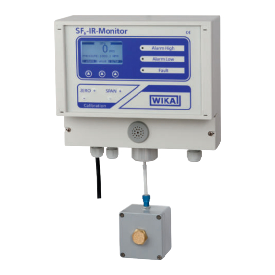
- Page 1 Emission monitor for SF gas, model GA35 Emissionswächter für SF -Gas, Typ GA35 ® Emission monitor for SF gas, model GA35...
- Page 2 Operating instructions model GA35 Page 3 - 36 Betriebsanleitung Typ GA35 Seite 37 - 70 Further languages can be found at www.wika.com © 2014 WIKA Alexander Wiegand SE & Co. KG All rights reserved. / Alle Rechte vorbehalten. ® WIKA is a registered trademark in various countries.
-
Page 3: Table Of Contents
6.9 Resetting to default settings ........25 WIKA operating instructions emission monitor for SF gas, model GA35... - Page 4 Contents 7. Faults ............26 8.
-
Page 5: General Information
Skilled personnel must have carefully read and understood the operating instructions prior to beginning any work. ■ The general terms and conditions contained in the sales documentation shall apply. ■ Subject to technical modifications. ■ Further information: WIKA operating instructions emission monitor for SF gas, model GA35... -
Page 6: Design And Function
2. Design and function 2. Design and function 2.1 Overview -IR-Monitor LC display Alarm and fault Alarm High indications Alarm Low Fault Navigation keys ZERO SPAN Calibration keys Calibration Terminal box Buzzer Cable gland for switching Cable gland for power outputs supply Cable gland for analogue... -
Page 7: Scope Of Delivery
Open terminal box Voltage supply Relay board Cover screws Sampling box Barbed fitting 2.2 Scope of delivery ■ Emission monitor model GA35 ■ Sampling box ■ Replacement filter ■ Operating instructions Cross-check scope of delivery with delivery note. WIKA operating instructions emission monitor for SF... -
Page 8: Safety
... points out useful tips, recommendations and information for efficient and trouble-free operation. 3.2 Intended use The model GA35 emission monitor is used for the continuous monitoring of the SF concentration in the ambient air. The instrument has been designed exclusively for operation in dry and closed areas. -
Page 9: Improper Use
Refrain from unauthorised modifications to the instrument. ▶ Do not use the instrument within hazardous areas. Any use beyond or different to the intended use is considered as improper use. WIKA operating instructions emission monitor for SF gas, model GA35... -
Page 10: Personnel Qualification
3. Safety 3.4 Personnel qualification WARNING! Risk of injury should qualification be insufficient Improper handling can result in considerable injury and damage to equip- ment. ▶ The activities described in these operating instructions may only be carried out by skilled personnel who have the qualifications described below. -
Page 11: Danger From Electrical Current
Product label The product label is located on the left edge of the case. WIKA Alexander Wiegand SE & Co. KG, 63911 Klingenberg, Germany Product: GA35, SF6-IR-Monitor Model: 2000 ppm Supply: 90-260VAC Power: 13W typical @ 50/60Hz ... - Page 12 3. Safety Symbols Before mounting and commissioning the instrument, ensure you read the operating instructions! Instruments bearing this mark comply with the relevant European directives. This marking on the instruments indicates that they must not be disposed of in domestic waste. The disposal is carried out by return to the manufac- turer or by the corresponding municipal authorities (see EU directive 2002/96/EC).
-
Page 13: Transport, Packaging And Storage
1. Place the instrument, along with the shock-absorbent material, in the packaging. 2. If stored for a prolonged period of time (more than 30 days), place a bag containing a desiccant inside the packaging. WIKA operating instructions emission monitor for SF gas, model GA35... -
Page 14: Commissioning
5. Commissioning 5. Commissioning Personnel: skilled electrical personnel 5.1 Requirements for the installation location Hang the emission monitor on a vertical and even wall. Provide sufficient space around the instrument so that cables and hose connections can be connected. 5.2 Wallmounting Required tools 3 screws (4 x 70 mm) 3 dowels (6) - Page 15 5. Commissioning Drilling drawing Hanger (13) WIKA operating instructions emission monitor for SF gas, model GA35...
-
Page 16: Connecting The Sampling Box
5. Commissioning 5.3 Connecting the sampling box Requirements for the measuring line Inner diameter: 4 ... 5 mm Max. length: 30 m Humidity can cause condensation in the measuring line if the measuring line cools towards the gas inlet. In this case, a water separator must be used. The material of the measuring line must be suitable for the application and the environ- mental conditions. -
Page 17: Connecting The Gas Outlet
Signal and power cables should be run in separate cable lines. Do not redistribute power cables within the connection compartment. Only connect one cable per terminal. Design the conductor cross-sections in accordance with the currents that are flowing. WIKA operating instructions emission monitor for SF gas, model GA35... - Page 18 5. Commissioning 5.5.1 Establishing the voltage supply CAUTION! Overvoltage on active current loop The instrument will be destroyed and the operational safety will no longer be ensured. ▶ Do not connect external voltage sources to the active current loop. Operation through a socket Fuse the socket in accordance with the max.
- Page 19 L = Phase N = Neutral line G = Protection line, GND O/P = Signal+ Active current loop Mains voltage 0V = Signal- L N G Microfuse (max. 3 A) WIKA operating instructions emission monitor for SF gas, model GA35...
- Page 20 5. Commissioning 5.5.3 Connecting the relay board The GA35 features two alarm relays and one error relay. The relays can be connected to external control and warning systems. The relays are suitable for small signals and high loads. → Connected load see chapter 10 “Specifications”.
-
Page 21: Switching On
The function of the navigation key will be shown in the navigation bar of the display. The functions will vary depending on the context. → For the placement of the keys, see chapter 2.1 “Overview” Navigation bar, context-dependent function of the navigation key WIKA operating instructions emission monitor for SF gas, model GA35... -
Page 22: Activating Numerical Measured Value Display
6. System settings 6.2 Activating numerical measured value display ▶ Select “VALUE”. » Numerical measured value display is active. 6.3 Activating graphical measured value display ▶ Select “GRAPH”. » Graphical measured value display is active. 6.4 Adjusting graphical measured value display The following parameters can be modified: X RANGE: time line ■... -
Page 23: Setting The Alarm
A higher contrast can make the display unreadable. Thus it should only be changed in steps. 1. Select “SETUP”. 2. Select “LCD SETTINGS”. 3. Set the contrast and confirm with “BACK”. » Contrast is set. WIKA operating instructions emission monitor for SF gas, model GA35... -
Page 24: Activating/Deactivating The Password Protection
6. System settings 6.7 Activating/deactivating the password protection 1. Select “SETUP”. 2. Select “SET PASSWORD”. 3. Select “PWD”. 4. Select “MODIFY”. 5. Set password. The password is made from an 8-digit combination of the navigation keys. 6. Activate (enable) or deactivate (disable) the password protection. »... -
Page 25: Resetting To Default Settings
25 % corresponds to 500 ppm Alarm Low idle polarity LED ON LED OFF LCD contrast Resolution 1. Select “SETUP”. 2. Select “LOAD DEFAULTS”. » Instrument is reset to default settings. WIKA operating instructions emission monitor for SF gas, model GA35... -
Page 26: Faults
7. Faults 7. Faults Personnel: skilled electrical personnel Error Fault Cause Measure number Alarm indication remains LED defect Send in for repair unlit Displayed gas Contact WIKA service concentration < -5 % Measuring range exceed- Contact WIKA service ed > 130 % of the measur- ing span (over range fault) Temperature of the Ambient tempera-... -
Page 27: Maintenance And Cleaning
Requirements for test gas Use certified test gas with known concentration and accuracy. ■ Concentration: 1,600 ... 2,000 ppm SF gas in air or synthetic air ■ Accuracy: ±2 % WIKA operating instructions emission monitor for SF gas, model GA35... - Page 28 8. Maintenance and cleaning Test assembly CAUTION! Overpressure at the gas inlet Overpressure at the gas inlet may lead to damage to the instrument! ▶ Never connect a pressurised gas container directly. Not even with a pressure reducer. ▶ Vent the gas inlet. The following test assembly enables intake of the test gases without any overpressure.
- Page 29 ▶ Do not use aggressive cleaning agents. ▶ Do not use any pointed and hard objects for cleaning. ▶ Clean the outside of the instrument with a soft, moist cloth. WIKA operating instructions emission monitor for SF gas, model GA35...
-
Page 30: Dismounting, Return And Disposal
9. Dismounting, return and disposal 9. Dismounting, return and disposal Personnel: skilled electrical personnel 9.1 Dismounting DANGER! Live parts Upon contact with live parts, there is a direct danger to life. ▶ Disassembly only by skilled electrical personnel. ▶ Before any work, disconnect the instrument from the mains. 1. - Page 31 This marking on the instruments indicates that they must not be disposed of in domestic waste. The disposal must be carried out by returning to the manufacturer or by the appropriate municipal authorities (see EU directive 2002/96/EC). WIKA operating instructions emission monitor for SF gas, model GA35...
-
Page 32: Specifications
10. Specifications 10. Specifications Specifications Model GA35 Measuring principle Two wavelengths, non-dispersive infrared sensor ≤ 250 m² Monitoring area Measuring range 0 ... 2,000 ppm Resolution 5 ppm ≤ 100 ppmv ±5 ppm Accuracy > 100 ppm ±2 % Permissible inlet pressure 800 ... - Page 33 CE conformity ■ Directives 2004/108/EC (EMC) 2006/95/EC (LVD) ■ Standards EN 50270:2006 EN 61000-6-3:2007 + A1:2011 EN 61010-1:2010 For further specifications see WIKA data sheet SP 62.15 and the order documentation. WIKA operating instructions emission monitor for SF gas, model GA35...
-
Page 34: Accessories
11. Accessories 11. Accessories Description Order no. Particle filter 14005137 Sampling box 14015834 Hose from PU (piece goods) 14007875... -
Page 35: Appendix 1: Menu Structure
Appendix 1: Menu structure WIKA operating instructions emission monitor for SF gas, model GA35... - Page 37 6.9 Auf Grundeinstellung zurücksetzen ....... . . 59 WIKA Betriebsanleitung Emissionswächter für SF -Gas, Typ GA35...
- Page 38 Anlage 1: Menüstruktur ..........69 WIKA Betriebsanleitung Emissionswächter für SF -Gas, Typ GA35...
-
Page 39: Allgemeines
Benutzer oder Besitzer des Gerätes weitergeben. ■ Das Fachpersonal muss die Betriebsanleitung vor Beginn aller Arbeiten sorgfältig durchgelesen und verstanden haben. ■ Es gelten die allgemeinen Geschäftsbedingungen in den Verkaufsunterlagen. ■ Technische Änderungen vorbehalten. ■ Weitere Informationen: WIKA Betriebsanleitung Emissionswächter für SF -Gas, Typ GA35... -
Page 40: Aufbau Und Funktion
2.1 Überblick -IR-Monitor LC-Display Alarm- und Alarm High Fehleranzeigen Alarm Low Fault Navigations- tasten ZERO SPAN Kalibrier- tasten Calibration Klemmkasten Summer Kabelverschraubung für Kabelverschraubung für Schaltausgänge Hilfsenergie Kabelverschraubung für Gaseinlass Gasauslass Analogausgang WIKA Betriebsanleitung Emissionswächter für SF -Gas, Typ GA35... -
Page 41: Lieferumfang
2. Aufbau und Funktion Klemmkasten geschlossen Deckelschrauben Klemmkasten geöffnet Spannungsversorgung Relaisplatine Deckelschrauben Probenahmebox Stecknippel-Verschraubung 2.2 Lieferumfang ■ Emissionswächter Typ GA35 ■ Probenahmebox ■ Austauschfilter ■ Betriebsanleitung Lieferumfang mit dem Lieferschein abgleichen. WIKA Betriebsanleitung Emissionswächter für SF -Gas, Typ GA35... -
Page 42: Sicherheit
... hebt nützliche Tipps und Empfehlungen sowie Informationen für einen effizienten und störungsfreien Betrieb hervor. 3.2 Bestimmungsgemäße Verwendung Der Emissionswächter Typ GA35 dient der kontinuierlichen Überwachung der -Konzentration in der Umgebungsluft. Das Gerät ist ausschließlich für den Gebrauch in trockenen und geschlossenen Räumen vorgesehen. -
Page 43: Fehlgebrauch
Fehlgebrauch des Gerätes kann zu gefährlichen Situationen und Verlet- zungen führen. ▶ Eigenmächtige Umbauten am Gerät unterlassen. ▶ Gerät nicht in explosionsgefährdeten Bereichen einsetzen. Jede über die bestimmungsgemäße Verwendung hinausgehende oder andersartige Benutzung gilt als Fehlgebrauch. WIKA Betriebsanleitung Emissionswächter für SF -Gas, Typ GA35... -
Page 44: Personalqualifikation
-Gas ist farb- und geruchlos, chemisch neutral, inert, nicht entflammbar und etwa fünfmal schwerer als Luft, nicht toxisch und nicht ozonschädigend. Detaillierte Angaben befinden sich in der IEC 60376 und IEC 61634. WIKA Betriebsanleitung Emissionswächter für SF -Gas, Typ GA35... -
Page 45: Gefahr Durch Elektrischen Strom
Beschädigtes oder defektes Gerät darf nur durch den Hersteller repariert werden. 3.7 Beschilderung, Sicherheitskennzeichnungen Typenschild Das Typenschild befindet sich am linken Gehäuserand. WIKA Alexander Wiegand SE & Co. KG, 63911 Klingenberg, Germany Product: GA35, SF6-IR-Monitor Model: 2000 ppm Supply: 90-260VAC Power: 13W typical @ 50/60Hz ... - Page 46 Richtlinien. Bei Geräten mit dieser Kennzeichnung wird darauf hingewiesen, dass diese nicht in den Hausmüll entsorgt werden dürfen. Die Entsorgung erfolgt durch Rücknahme bzw. durch entsprechende kommunale Stellen (siehe EU-Richtlinie 2002/96/EG). WIKA Betriebsanleitung Emissionswächter für SF -Gas, Typ GA35...
-
Page 47: Transport, Verpackung Und Lagerung
Gerät wie folgt verpacken und lagern: 1. Das Gerät mit dem Dämmmaterial in der Verpackung platzieren. 2. Bei längerer Einlagerung (mehr als 30 Tage) einen Beutel mit Trocknungsmittel der Verpackung beilegen. WIKA Betriebsanleitung Emissionswächter für SF -Gas, Typ GA35... -
Page 48: Inbetriebnahme
5. Gerät ausrichten. 6. Bohrungen anzeichnen. 7. Gerät abhängen. 8. Bohrungen bohren und mit Dübeln versehen. 9. Gerät aufhängen. 10. Gerät anschrauben. Bei Steinwänden sind die Bohrungen immer mit Dübeln zu versehen. WIKA Betriebsanleitung Emissionswächter für SF -Gas, Typ GA35... - Page 49 5. Inbetriebnahme Bohrskizze Aufhänger (13) WIKA Betriebsanleitung Emissionswächter für SF -Gas, Typ GA35...
-
Page 50: Probenahmebox Anschließen
2. Messleitung bis Anschlag über die Stecknippel-Verschraubung schieben. 3. Stecknippel-Verschraubung festziehen. 4. Festen Sitz prüfen. 5. Messleitung bis Anschlag über den Anschlusszapfen des Gaseinlasses am Emissi- onswächter schieben. 6. Festen Sitz prüfen. 7. Probenahmebox am Aufstellort anbringen. WIKA Betriebsanleitung Emissionswächter für SF -Gas, Typ GA35... -
Page 51: Gasauslass Anschließen
Kabeldurchmessern die Kabelverschraubungen durch geeignete erset- zen. Signal- und leistungsführende Kabel in getrennten Leitungssträngen verlegen. Leistungsführende Kabel nicht innerhalb des Klemmraums umverteilen. Pro Klemme nur eine Leitung anschließen. Leitungsquerschnitte entsprechend der fließenden Ströme auslegen. WIKA Betriebsanleitung Emissionswächter für SF -Gas, Typ GA35... - Page 52 5. Überprüfen, ob die Verschraubungen fest sitzen und Zugentlastung bieten. 6. Klemmkasten schließen. Platine Spannungsversorgung L = Phase N = Neutralleiter G = Schutzleiter, GND O/P = Signal+ Aktive Netzspannung Stromschleife 0V = Signal- L N G Feinsicherung (max. 3 A) WIKA Betriebsanleitung Emissionswächter für SF -Gas, Typ GA35...
- Page 53 5. Überprüfen, ob die Verschraubungen fest sitzen und Zugentlastung bieten. 6. Klemmkasten schließen. Platine Spannungsversorgung L = Phase N = Neutralleiter G = Schutzleiter, GND O/P = Signal+ Aktive Stromschleife Netzspannung 0V = Signal- L N G Feinsicherung (max. 3 A) WIKA Betriebsanleitung Emissionswächter für SF -Gas, Typ GA35...
- Page 54 5. Inbetriebnahme 5.5.3 Relaisplatine anschließen Der GA35 verfügt über zwei Alarmrelais und ein Fehlerrelais. Die Relais können an externe Steuerungs- und Warnanlgen angeschlossen werden. Die Relais eignen sich für kleine Signale und hohe Leistungen. → Anschlussleistungen siehe Kapitel 10 „Technische Daten“.
-
Page 55: Einschalten
Navigationstaste unterhalb des Displays drücken, um im Menü zu navigieren. Die Funktion der Navigationstaste wird in der Navigationsleiste des Displays angezeigt. Die Funktionen ändern sich kontextbezogen. → Platzierung der Tasten siehe Kapitel 2.1 „Übersicht“ Navigationsleiste, kontextbezogene Funktion der Navigationstaste WIKA Betriebsanleitung Emissionswächter für SF -Gas, Typ GA35... -
Page 56: Numerische Messwertdarstellung Aktivieren
Ausgefüllt (unterhalb der Messkurve schwarz gefüllt) Voraussetzung: Grafische Messwertdarstellung ist ausgewählt 1. „GRAPH“ drücken. » Navigationsleiste zeigt ersten Parameter an. 2. Parameter auswählen (Pfeil). 3. Parameter einstellen und mit „BACK“ bestätigen. » Grafische Messwertdarstellung ist angepasst. WIKA Betriebsanleitung Emissionswächter für SF -Gas, Typ GA35... -
Page 57: Alarm Einstellen
6.6 Kontrast einstellen Ein hoher Kontrast kann das Display unlesbar machen. Daher nur schrittweise ändern. 1. „SETUP“ auswählen. 2. „LCD SETTINGS“ auswählen. 3. Kontrast einstellen und mit „BACK“ bestätigen. » Kontrast ist eingestellt. WIKA Betriebsanleitung Emissionswächter für SF -Gas, Typ GA35... -
Page 58: Passwortschutz Aktivieren/Deaktivieren
Diese Einstellung beeiflusst nur die Anzeige. Einstellbare Auflösungen: 0,1 ppm , 1 ppm , 5 ppm 5 ppm ist empfohlen. 1. „SETUP“ auswählen. 2. „RESOLUTION“ auswählen. 3. Auflösung einstellen und mit „BACK“ bestätigen. » Auflösung ist eingestellt. WIKA Betriebsanleitung Emissionswächter für SF -Gas, Typ GA35... -
Page 59: Auf Grundeinstellung Zurücksetzen
Alarm Low limit 25 % entspricht 500 ppm Alarm Low idle polarity LED ON LED OFF LCD contrast Resolution 1. „SETUP“ auswählen. 2. „LOAD DEFAULTS“ auswählen. » Gerät ist auf Grundeinstellung zurückgesetzt. WIKA Betriebsanleitung Emissionswächter für SF -Gas, Typ GA35... -
Page 60: Störungen
% des Nominalwertes tieren Probenahme der Neustart des Gerätes. Spannekalibrierung zu Nullpunkt-/Spannekalib- nahe am Nullpunkt rierung durchführen Checksumme der Gespeicherten Koeffizienten ungleich 1 Koeffizienten prüfen Durchflussrate nicht in WIKA-Service kontak- Ordnung (Flow Fault) tieren WIKA Betriebsanleitung Emissionswächter für SF -Gas, Typ GA35... -
Page 61: Wartung Und Reinigung
Wartungsintervall: 2 Jahre oder nach Bedarf. Anforderungen an Prüfgas Zertifiziertes Prüfgas mit bekannter Konzentration und Genauigkeit verwenden. ■ Konzentration: 1.600 ... 2.000 ppm SF -Gas in Luft bzw. synthetischer Luft ■ Genauigkeit: ±2 % WIKA Betriebsanleitung Emissionswächter für SF -Gas, Typ GA35... - Page 62 1. Prüfaufbau gemäß Abbildung errichten. Gaseinlass des Emissionswächters noch nicht anschließen. 2. Gaszylinder öffnen. 3. Prüfaufbau auf permanenten Gasdurchfluss überprüfen (z. B. mit angefeuchtetem Finger oder Durchflussmesser). 4. Gaszylinder schließen. 5. Prüfaufbau an Gaseinlass anschließen. WIKA Betriebsanleitung Emissionswächter für SF -Gas, Typ GA35...
- Page 63 Verwendung nicht geeigneter Reinigungsmittel Nicht geeignete Reinigungsmittel können das Gerät beschädigen. ▶ Keine aggressiven Reinigungsmittel verwenden. ▶ Keine harten und spitzen Gegenstände zur Reinigung verwenden. ▶ Gerät von außen mit einem weichen, feuchten Tuch reinigen. WIKA Betriebsanleitung Emissionswächter für SF -Gas, Typ GA35...
-
Page 64: Demontage, Rücksendung Und Entsorgung
Zur Rücksendung des Gerätes die Originalverpackung oder eine geeignete Transport- verpackung verwenden. Um Schäden zu vermeiden: ▶ Gerät zu allen Seiten der Transportverpackung gleichmäßig dämmen. Hinweise zur Rücksendung befinden sich in der Rubrik „Service“ auf unserer lokalen Internetseite. WIKA Betriebsanleitung Emissionswächter für SF -Gas, Typ GA35... - Page 65 Abfallbehandlungs- und Entsorgungsvorschriften umweltgerecht entsorgen. Bei Geräten mit dieser Kennzeichnung wird darauf hingewiesen, dass diese nicht in den Hausmüll entsorgt werden dürfen. Die Entsorgung erfolgt durch Rücknahme bzw. durch entsprechende kommunale Stellen (siehe EU-Richtlinie 2002/96/EG). WIKA Betriebsanleitung Emissionswächter für SF -Gas, Typ GA35...
-
Page 66: Technische Daten
(2 x Alarm, 1 x Fehler) Schaltvermögen: AC 260 V, 8 A (resistive Last) DC 30 V, 8 A (resistive Last) Warnton Summer, ertönt bei Über- oder unterschreiten der eingestellten Alarmwerte (Wirkrichtung einstellbar, IDLE POLARITY) WIKA Betriebsanleitung Emissionswächter für SF -Gas, Typ GA35... - Page 67 B x H x T: 260 x 280 x 140 mm Gewicht 2,5 kg CE-Konformität ■ Richtlinien 2004/108/EG (EMV) 2006/95/EG (NSR) ■ Normen EN 50270:2006 EN 61000-6-3:2007 + A1:2011 EN 61010-1:2010 Weitere technische Daten siehe WIKA-Datenblatt SP 62.15 und Bestellunterlagen. WIKA Betriebsanleitung Emissionswächter für SF -Gas, Typ GA35...
-
Page 68: Zubehör
11. Zubehör 11. Zubehör Beschreibung Bestell-Nr. Partikelfilter 14005137 Probenahmebox 14015834 Schlauch aus PU (Meterware) 14007875 WIKA Betriebsanleitung Emissionswächter für SF -Gas, Typ GA35... -
Page 69: Anlage 1: Menüstruktur
Anlage 1: Menüstruktur WIKA Betriebsanleitung Emissionswächter für SF -Gas, Typ GA35...
Need help?
Do you have a question about the GA35 and is the answer not in the manual?
Questions and answers