Table of Contents
Advertisement
Quick Links
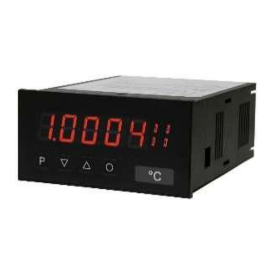
User manual IM2-1F
Frequency input: 0.01 Hz to 999.99 kHz / 0.01 Hz to 9.9999 kHz / 0-2.500 kHz
Connection for Namur, NPN/PNP with HTL- or TTL-output or for
position survey via incremental encoder
Technical features:
• red display of -19999...99999 digits (optional: green, orange or blue display)
• minimal installation depth: 70 mm without plug-in terminal
• min/max memory
• adjustment via factory default or directly on the sensor signal
• 30 adjustable supporting points
• display flashing at threshold undercut or exceedance
• simplified parameterisation U/min with only 3 parameters
• Schmitt-trigger-input
• zero-key for triggering of Hold, Tara
• permanent min/max-value recording
• digital frequency filter for contact bounce suppression and interference suppresion
• frequency filter with varying pulse-duty factor
• volume metering (totaliser) for frequencies up to 1 kHz (accurate to a pulse)
• mathematical function like reciprocal value, square root, rounding
• sliding averaging with an optional dynamic display filter
• setpoint generator
• brightness control
• programming interlock via access code
• protection class IP65 at the front
• plug-in terminal
• sensor supply
• galv. isolated digital input
• option: relay outputs
• option: analog output
• accessories: PC-based configuration-kit PM-TOOL incl. CD & USB-adapter
Advertisement
Table of Contents

Related Manuals for ICS Schneider Messtechnik IM2-1F


Summary of Contents for ICS Schneider Messtechnik IM2-1F
- Page 1 User manual IM2-1F Frequency input: 0.01 Hz to 999.99 kHz / 0.01 Hz to 9.9999 kHz / 0-2.500 kHz Connection for Namur, NPN/PNP with HTL- or TTL-output or for position survey via incremental encoder Technical features: • red display of -19999…99999 digits (optional: green, orange or blue display) •...
- Page 2 Identification STANDARD-TYPES ORDER NUMBER IM2-1FR5B.0307.570xD Frequency IM2-1FR5B.0007.670xD Housing size: 96x48 mm Options – breakdown of order code: IM 2- 1 F R 5 B. 0 3 0 7. 5 7 0 x D Basic type IM2 Dimension D physical unit Installation depth 89 mm, incl.plug-in terminal Version...
-
Page 3: Table Of Contents
Contents 1. Brief description 2. Assembly 3. Electrical connection 4. Function description and operation 4.1. Programming software PM-TOOL 5. Setting up the device 5.1. Switching on 5.2. Standard parameterisation (flat operation level) Value assignment for the triggering of the signal input 5.3. -
Page 4: Brief Description
1. Brief description 1. Brief description The panel meter IM2-1F can evaluate pulses in many different ways and shows the result in the 5-digit LED-display. Available options are: frequency coverage with optional filters, summate of pulses or display values via the time, detection of a rotational speed or collection of a position via an incremental encoder. -
Page 5: Assembly
2. Assembly 2. Assembly Please read the Safety advices on page 43 before installation and keep this user manual for future reference. Gap for physical unit 1. After removing the fixing elements, insert the device. 2. Check the seal to make sure it fits securely. 3. -
Page 6: Electrical Connection
3. Electrical connection 3. Electrical connection Type IM2-1FR5B.0307.470xD – supply of 115 VAC Type IM2-1FR5B.0307.570xD – supply of 230 VAC 230 VAC Sensor 115 VAC supply Pulse input 1 Pulse input 2 24 VDC 3-wire 3-wire sensor sensor Digital Namur Namur input Options... - Page 7 3. Electrical connection Type IM2-1FR5B.0007.670xD – supply of 10-30 VDC galv. isolated 10-30 VDC Pulse input 1 Pulse input 2 3-wire 3-wire sensor sensor Namur Namur Options: alternatively to analog output Sensor Analog output supply Digital input alternatively to pulse input 2 Relais 1 Relais 2 Pulse output...
- Page 8 3. Electrical connection M3-devices Below please find some connection examples with practical applications: Namur NA MU R 10-30 VDC Namur NAMUR 230 VAC 3-wire PNP 3-wire 10-30 VDC 3-wire PNP 3-wire 230 VAC...
- Page 9 3. Electrical connection 3-wire NPN Pull-up (extern) 2,7 k 0,5 W 10-30 VDC 3-wire 3-wire NPN Pull-up (extern) 2,7 k 0,5 W 3-wire 230 VAC Incremental encoder with analog output 4-20 mA Incremental encoder 10-30 VDC Incremental encoder (max. 50 mA current consumption) Incremental encoder 115VAC external...
-
Page 10: Function Description And Operation
4. Function and operation description 4. Function and operation description Operation The operation is divided into three different levels. Menu level (delivery status) This level is for the standard settings of the device. Only menu items which are sufficent to set the device into operation are displayed. -
Page 11: Programming Software Pm-Tool
4. Function and operation description Function chart: 4.1. Parameterisation software PM-TOOL: Part of the PM-TOOL are the software on CD and an USB-cable with device adapter. The connection is done via a 4-pole micromatch-plug on the back side of the device, to the PC-side the connection ist done via an USB plug. -
Page 12: Setting Up The Device
5. Setting up the device 5. Setting up the device 5.1. Switching-on Once the installation is complete, start the device by applying the voltage supply. Before, check once again that all electrical connections are correct. Starting sequence For 1 second during the switching-on process, the segment test ( ) is displayed, followed by an indication of the software type and, after that, also for 1 second, the software version. - Page 13 5. Setting up the device Menu level Parameterisation level Setting end value of the measuring range, Default: 9.9999 Hz 99.999 Hz 999.99 Hz 9.9999 kHz 99.999 kHz 999.99 kHz Choose between six different frequency ranges. Confirm the selection with [P] and the display switches back to menu level.
- Page 14 5. Setting up the device Menu level Parameterisation level Setting the decimal point, Default: The decimal point on the display can be moved with [▲] [▼] and confirmed with [P]. The display then switches back to the menu level again. Setting up the display time, Default: then...
- Page 15 5. Setting up the device Menu level Parameterisation level Setting of the pulse delay, Default: With the pulse delay of 0–250 seconds (max), frequencies can be collected, which are even smaller than by the predetermined measuring time of the device. If e.g. a delay of 250 seconds is set, this means that the device waits up to 250 seconds for an edge, before it assumes a 0 Hz frequency.
- Page 16 5. Setting up the device Menu level Parameterisation level Setting up the initial value of the analog output, Default: The final value is adjusted from the smallest digit to the highest digit with [▲] [▼] and digit by digit confirmed with [P]. A minus sign can only be parameterised on the highest digit.
- Page 17 5. Setting up the device Menu level Parameterisation level Hysteresis for limit values, Default: The delayed reaction of the alarm is the difference to the threshold value, which is defined by the hysteresis. Function for threshold value undercut / exceedance, Default: A limit value undercut is selected with (for LOW = lower limit value), a limit...
-
Page 18: Programming Interlock
5. Setting up the device Menu level Parameterisation level 5.3. Programming interlock „ “ Activation / deactivation of the programming lock or completion of the standard parameterization with change into menu group level (complete function range), Default: Choose between the deactivated key lock (works setting) and the activated key lock , or the menu group level... -
Page 19: Extended Parameterisation (Professional Operation Level)
5. Setting up the device 5.4. Extended parameterisation (Professional operation level) 5.4.1. Signal input parameters Menu group level Menu level Menu level Parameterisation level Selection of the input signal, Default: If the scaling of the device is done via (Sensor calibration), the frequency range needs to be preset under and is adjusted by application of the final value / initial value. - Page 20 5. Setting up the device Menu level Parameterisation level Setting the end value of the measuring range, Default: 9.9999 Hz 99.999 Hz 999.99 Hz 9.9999 kHz 999.99 99.999 kHz Choose between 6 different frequency ranges. Confirm the selection with [P] and the display switches back to menu level.
- Page 21 5. Setting up the device Menu level Parameterisation level Setting the decimal point, Default: The decimal point on the display can be moved with [▲] [▼] and confirmed with [P]. The display then switches back to the menu level again. Setting up the display time, Default: then...
- Page 22 5. Setting up the device Menu level Parameterisation level Setting up the pulse delay, Default: With the pulse delay of 0–250 seconds (maximum), frequencies that are even smaller than by the predetermined measuring time of the device, can be collected. If e.g.
- Page 23 5. Setting up the device Menu level Parameterisation level Number of additional setpoints, Default: 30 additional setpoints can be defined to the initial value and final value, so linear sensor values are not linearised. Only activated setpoint parameters are displayed. Display values for setpoints, Under this parameter setpoints are defined according to their value.
-
Page 24: General Device Parameters
5. Setting up the device Menu level Parameterisation level Input variable of process value, Default: This parameter controls the device via the analog input signals repectively or via the digital signals of the interface = RS232/RS485 (Modbus protocol). Confirm the selction with [P] and the device changes back into menu level. - Page 25 5. Setting up the device Menu level Parameterisation level Arithmetic, Default: Root extraction Reciprocal Square With this function the calculated value, not the measuring value, is shown in the display. Calculation types rEZIP = (Final value*Final value)/Display value rAdiC = Root(Display value*Final value) SqUAr = (Display value)²/Final value Advice: The denominator of fractions should not be 0 because a division by 0 is not possible.
- Page 26 5. Setting up the device Menu level Parameterisation level Zero point slowdown, Default: At the zero point slowdown, a value range around the zero point can be preset, so the display shows a zero. If e.g. a 10 is set, the display would show a zero in the value range from -10 to +10;...
- Page 27 5. Setting up the device Menu level Parameterisation level Display, Default: With this function the current measurand, min/max-value, totaliser value, the process-controlled Hold-value, the sliding average value, the constant value or the difference between constant value and current value can be allocated to the display.
- Page 28 5. Setting up the device Menu level Parameterisation level Assignment (deposit) of key functions, Default: For the operation mode, special functions can be deposited on the navigation keys [▲] [▼], in particular this function is made for devices in housing size 48x24mm which do not have a 4th key ([O]-key).
-
Page 29: Safety Parameters
5. Setting up the device Menu level Parameterisation level Continuation Special function [O]-key, Default: Advice: is activated only, if is selected under parameter shows the measuring value for approx. 7 seconds, after this the device switches back on the parameterised display value. The same goes for , here the sliding average values will be displayed. - Page 30 5. Setting up the device Menu level Parameterisation level Master code, Default: By entering the device will be unlocked and all parameters are released. Release/lock analog output parameters, Default: Analog output parameter can be locked or released for the user: - At the initial or final value can be changed in operation mode.
-
Page 31: Analog Output Parameters
5. Setting up the device 5.4.4. Analog output parameters Menu group level Menu level Menu level Parameterisation level Selection reference of analog output, Default: The analog output signal can refer to different functions, in detail these are the current measurand, the min-value, the max-value, the totaliser function / sum function, the constant value or the difference between current measurand and constant value. - Page 32 5. Setting up the device Menu level Parameterisation level Setting the initial value of the analog output, Default: The initial value is adjusted from the smallest to the highest digit with [▲] [▼] and confirmed digit per digit with [P]. A minus sign can only be parameterised on the leftmost digit.
-
Page 33: Relay Functions
5. Setting up the device 5.4.5. Relay functions Menu group level Menu level Menu level Parameterisation level Alarm relay 1, Default: …. …. Each setpoint (optional) can be linked up via 4 alarms (by default). This can either be inserted at activated alarms or deactivated alarms . - Page 34 5. Setting up the device Menu level Parameterisation level Alarms for relay 1, Default: …. The allocation of the alarms to relay 1 happens via this parameter, one alarm or a group of alarms can be chosen. With [P] the selection is confirmed and the device changes into menu level.
-
Page 35: Alarm Parameters
5. Setting up the device Menu level Parameterisation level Alarms for relay 2, Default: …. The allocation of the alarms for relay 2 happens via this parameter, one alarm or a group of alarms can be chosen. With [P] the selection is confirmed and the device changes into menu level. - Page 36 5. Setting up the device Menu level Parameterisation level Threshold values / limit values, Default: For both limit values, two different values can be parameterized. With this, the parameters for each limit value are called up one after another. Hysteresis for limit values, Default: For all limit values exists a hysteresis function, that reacts according to the settings (threshold exceedance / threshold undercut).
-
Page 37: Totaliser (Volume Metering)
5. Setting up the device Menu level Parameterisation level Back to menu group level, With [P] the selection is confirmed and the device changes into menu group level The same applies to 5.4.7. Totaliser (Volume measurement) Menu group level Menu level Menu level Parameterisation level Totaliser state,... - Page 38 5. Setting up the device Menu level Parameterisation level Setting up the decimal point for the totaliser, Default: The decimal point of the device can be adjusted with the navigation keys [▲] [▼]. With [P] the selection is confirmed and the device changes into menu level. Totaliser reset, Default: The reset value is adjusted from the smallest to the highest digit with the...
-
Page 39: Reset To Factory Settings
6. Reset to factory settings / 7. Alarms/Relays 6. Reset to factory settings To return the unit to a defined basic state, a reset can be carried out to the default values. The following procedure should be used: • Switch off the power supply •... - Page 40 7. Alarms / Relays Quiescent current By quiescent current the alarm S1-S2 is on below the threshold and switched off on reaching the threshold. Switching-on delay The switching-on delay is activated via an alarm and e.g. switched 10 seconds after reaching the switching threshold, a short-term exceedance of the switching value does not cause an alarm, respectively does not cause a switching operation of the relay.
-
Page 41: Programmer Examples
8. Programmer examples 8. Programmer examples Example for the rotation speed adjustment: In this application the rotation speed of an axis shall be collected via a toothed wheel with 30 sprockets, per Namur sensor. It is then displayed with one position after decimal point and the dimension rpm. - Page 42 8. Programmer examples Examples: Adjustment according to number of sprockets at unknown rotation speed. - nearly 100% of the rotation speeds are in the range of 0 to 30.000 r.p.m. - the number of sprockets varies (without gearing) between 1 and 100 - in automation, the frequency supply never exceeds 10 kHz (rather 3 kHz) Assume a rotation speed of 60 r.p.m.
-
Page 43: Rotation Speed
8. Programmer examples Example: Rotation speed of a machine shaft There are 4 sprockets on one machine shaft. Applied in an angle of 90° to each other and to the rotation speed measurement. The sprockets are collected via a proximity switch and evaluated by the frequency device, which shall display the rotation speed in U/min. -
Page 44: Technical Data
9. Technical data 9. Technical data Housing Dimensions 96x48x70 mm (WxHxD) 96x48x89 mm (WxHxD) incl. plug-in terminal Panel cut-out 92.0 +0.8 x 45.0 +0.6 Wall thickness up to 15 mm Fixing screw elements Material PC Polycarbonate, black, UL94V-0 Sealing material EPDM, 65 Shore, black Protection class Standard IP65 (Front), IP00 (back side) - Page 45 9. Technical data Accuracy Temperature drift 50 ppm / K Measuring time 0.1…10.0 seconds, respectively optional pulse delay 250 seconds Measuring principle Frequency measuring / pulse width modulation Measuring error 0.05% of measuring range; ± 1 digit Resolution approx. 19 bit per measuring range Output Sensor supply 24 VDC / 50 mA...
-
Page 46: Safety Advices
Please inform the supplier immediately of any damage. Installation The IM2-1F-device must be installed by a suitably qualified specialist (e.g. with a qualification in industrial electronics). Notes on installation •... -
Page 47: Error Elimination
11. Error elimination 11. Error elimination Error description Measures • The device shows The input frequency is too high for the selected frequency a permanent range. Correct range according to this. • overflow Disturbing pulses lead to an increased input frequency, activate fi.frq at smaller frequencies or shield the senor line. - Page 48 11. Error elimination Error description Measures • The device shows The device located an error in the configuration memory, HELP in the excecute a reset to the default values and set up the device 7-segment display according to your application. •...
Need help?
Do you have a question about the IM2-1F and is the answer not in the manual?
Questions and answers