Table of Contents
Advertisement
Quick Links
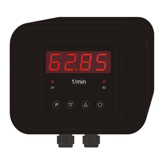
User manual IAKV-2VR4C
Standard signal metering in wall-mounting case
Technical features:
• Digit height: 20 mm
• Colour: red
• Range of display: -999...9999
• Wall-mounting case: black, made of ABS-plastic
• Protection class: IP65
• Sizes: 160 x 130 mm, Depth 60 mm
• Supply: 230 VAC
• Sensor supply: 24 V / 50 mA
• Measuring input: 0 -10 VDC, 0/4 – 20 mA
• 2 relay output
• 10 point linearisation
• Offset presetting
• Tara- / Hold-function
Advertisement
Table of Contents

Related Manuals for ICS Schneider Messtechnik IAKV-2VR4C


Summary of Contents for ICS Schneider Messtechnik IAKV-2VR4C
- Page 1 User manual IAKV-2VR4C Standard signal metering in wall-mounting case Technical features: • Digit height: 20 mm • Colour: red • Range of display: -999…9999 • Wall-mounting case: black, made of ABS-plastic • Protection class: IP65 • Sizes: 160 x 130 mm, Depth 60 mm •...
-
Page 2: Table Of Contents
Contents Brief description ........................3 Safety advices ..........................3 2.1. Proper use ..........................3 2.2. Control of the device.........................3 2.3. Installation..........................3 2.4. Notes on installation .........................3 Assembly ..........................4 3.1. Dimensions ..........................4 3.2. Assembly of the wall-type housing ...................4 3.3. Mounting holes .........................5 Electrical connection.........................5 4.1. -
Page 3: Brief Description
Brief description 1. Brief description With the digital indicator IAKV-2VR4C standard signals DC 0/4 … 20 mA or DC 0 … 5/10 V can be measured. The 4-digit display shows the measurements or the scaled value of the measurement. During programming the display is used to indicate the set values and the user prompts. -
Page 4: Assembly
After successfully mounting the lower section, lift up the upper section with the IAKV-2VR4C and place it on the lower section. Using the 4 fixing screws, screw the upper part to the lower part. Take care that the screws are completely tightened in order to attain protection IP66. -
Page 5: Mounting Holes
Electrical connection 3.3. Mounting holes 160,0 139,0 Maßbild der Befestigungslöcher 4. Electrical connection Connect all the signals needed for operation to the back terminal strips. The connecting terminals are provided with a reference grid of 5.08 mm as clamp terminals. These enable the connection of wires up to 2.5 mm². -
Page 6: 9-Pole Connector Strip
Electrical connection 4.2. 9-pole connector strip Via the connector strip with the terminal numbers 6 to 14 the voltage supply/auxiliary power of the device and the two relay outputs are connected. Relay 1 (S1) Auxiliary power Relay 2 (S2) Normally Normally Normally Normally... -
Page 7: Connection Examples
Operation 4.4. Connection examples This section gives a few examples of practical connections. Other connection options can be combined from the various examples. Measuring a current signal (4-20 mA) from a 2-wire transmitter, using the sensor supply. Measurement of a voltage signal (0-5 V or 0-10 V) from a 3-wire transmitter using the sensor supply 24 VDC. -
Page 8: Operation
Dimension gap 7-segment display Front view 5.1.1. Keys The IAKV-2VR4C has 3 keys, with which you can parameterise and call up various functions during operation. 1 Program key With the program key, you can call up the programming mode or perform various functions in the programming mode. -
Page 9: Switching On
Operation 5.2. Switching on Before switching on you have to check all the electrical connections to make sure they are correct. On completion of the installation, the device can be switched on by applying the power supply. 5.3. Starting sequence During the switching-on process a segment test is performed for approx. -
Page 10: Relay
Operation 5.6. Relay With the aid of the LED below the 7-segment display, you can view the switching state of the relay. An active relay is indicated by the relevant LED lighting up. The relays have the following properties with regard to their switching properties: Setpoint output Deactivated, activated Threshold... -
Page 11: Optical Response Display Flashing
Operation 5.6.1. Optical response display flashing The switching on of one or more alarm outputs can also be set to trigger a flashing of the display to enhance the optical response. 11/24... -
Page 12: Programming
Display of e.g. program number 0 6.1. Programming procedure The entire programming of the IAKV-2VR4C is done by the steps described below. Change to the programming mode Pushing the [P] key changes to programming mode. The unit goes to the lowest available program number. -
Page 13: Change To The Operating Mode
Measuring input 6.2. The IAKV-2VR4C is equipped with a measuring input for standard signals that enables standardised signals (e.g. 4 … 20 mA) from all kinds of different measuring transmitters on the market to be measured directly. -
Page 14: Sensor Calibration
Programming permanently in the unit. It means that a pre-adjusted transmitter can be operated directly with the indicator without any need to previously connect the signal to be measured to the indicator. The indicator can be scaled freely according to the physical dimension to be measured. 6.2.2. -
Page 15: Device Parameter
Programming 7. Device parameter The IAKV-2VR4C has a number of unit parameters with which the function of the indicator can be adjusted to the relevant measuring tasks. Because of the large number of these settings and the limited possibility of displaying them on the 7-segment display, the parameters have been given consecutive numbers. -
Page 16: Measuring Time Pn14
The parameterised user level PN52 is active as long as the locking code PN51 and the access code PN50 are different. On delivery of the IAKV-2VR4C both parameters are set to 0000, so that the programming lock is deactivated. -
Page 17: Allocation Of Functions Of The Zero Key Pn54
Programming 7.1.9. Allocation of functions of the zero key PN54 By pushing of the zero key functions like e.g. TARA and HOLD can be actuated or a offset shift can be preset. By allocation of TARA the key needs to be pushed for at least 1 second. The device confirms the function by showing „0000“... -
Page 18: Program Number Table
Program number table 8. Program number table The program table lists all the program numbers (PN) with their function, range of values, default values and user level. PN Function Range of value Def- User ault level Channel 1 Measuring input Current, Voltage 0 = Sensor calibration Parameters 1 to 4 make use of the... - Page 19 Program number table PN Function Range of value Def- User ault level Delay type 0 = none 1 = switch-on delay 2 = switch-off delay 3 = switch-on/-off delay Setpoint 2 Setpoint 2 0 = deactivated 1 = activated Threshold -999...9999 1000 Hysterisis...
-
Page 20: Technical Data
Technical data 9. Technical data Housing Dimensions 160 x 130 x 60 mm (B x H x T) Weight max. 430 g Fixing 4 fixing holes in the lower section of the housing Material ABS (UL94V-0) Colour Black, RAL7035 Protection class Standard IP65 Connection abatable screw terminals;... - Page 21 Technical data Power consumption max. 8 VA Memory Parameter memory EEPROM Data life >20 years Ambient conditions Working temperature 0...60 °C Storing temperature -20...80 °C rel. humidity ≤ 75 % on years average without dew Climatic density DIN 61326 CE-sign Conformity to 89/336/EWG Safety standard DIN 61010...
-
Page 22: Trouble Shooting
Trouble shooting 10. Trouble shooting The following list gives the recommended procedure for dealing with faults and locating their possible cause. 10.1. Questions and answers The unit permanently indicates overflow „ ¯ ¯ ¯ ¯ “. The input has a very high measurement, check the measuring circuit. The unit permanently indicates underflow „...
Need help?
Do you have a question about the IAKV-2VR4C and is the answer not in the manual?
Questions and answers