Table of Contents
Advertisement
Quick Links
Advertisement
Table of Contents

Related Manuals for ICS Schneider Messtechnik HYDROTECHNIK MultiHandy 2025


Summary of Contents for ICS Schneider Messtechnik HYDROTECHNIK MultiHandy 2025
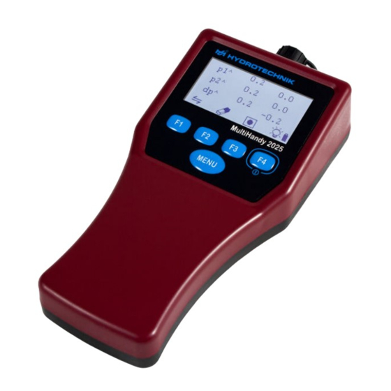
- Page 1 MultiHandy 2025 Operating Instructions...
-
Page 2: Table Of Contents
OPERATING INSTRUCTIONS Basics ......1 Resetting menu language ....20 Proper use . -
Page 3: Basics
1 Basics 1 BASICS Disposal of the measuring instrument This instruction manual is part of the MultiHandy 2025 Disposal information instrument. It contains the information necessary for Do not dispose of this product with your safe use. Read this manual before starting up the in- household waste. -
Page 4: Description Of The Measuring Instrument
2 Description of the measuring instrument 2 DESCRIPTION OF THE MEASURING 2.2 Measuring instrument INSTRUMENT This section describes the scope of delivery, connec- tions, keys and the display of the measuring instru- ment. 2.1 Measuring instrument case Display Menu key Function keys On/off button (F4) The MultiHandy 2025 is a dual-channel measuring in-... -
Page 5: Rear Side
2 Description of the measuring instrument The instrument is equipped with an internal memory. Battery compartment Up to 5 measurement series with up to 60,000 meas- urement points each can be saved in the measuring instrument. You can connect the measuring instrument to a PC and charge it using the USB interface. -
Page 6: Connections
2 Description of the measuring instrument 2.4 Connections 2.6 Display The display shows measurement values, menu en- tries, status icons and function key icons. Measurement channel 2 USB interface Measurement channel 1 ISDS icon Function key icons For information on permissible input signals and Channel name voltage supply, see Technical data, page 21. -
Page 7: Keys, Icons And Functions
3 Start-up 2.7 Keys, icons and functions 3 START-UP 3.1 Charging measuring instrument Switches instrument on. The batteries of the measuring instrument must be Opens main menu. charged before it is switched on for the first time. Selects marked entry. How to charge the measuring instrument Switches display illumination on/off. -
Page 8: Basic Settings
3 Start-up 3.2 Basic settings The display shows the firmware version number and serial number of the measuring instrument. After you have charged the measuring instrument, The display then shows the calibration notice. you can switch it on. When you switch on the measur- ing instrument for the first time, you are requested to define the basic settings. -
Page 9: Time And Date
3 Start-up 3.3 Time and date Press to select [F1] Date to open the [MENU] DATE MENU How to set the time and date Set the date format and date: Press and use to select the • Use to select and press [MENU] [F1]... -
Page 10: Calibration Interval
4 Calibration interval 4 CALIBRATION INTERVAL Press to select the entry and [F1] Calibration to open the menu. [MENU] CALIBRATION The measuring instrument was calibrated before it was shipped by the manufacturer. The calibration in- terval is the period of time after which the measuring instrument is to be re-calibrated by the manufacturer. -
Page 11: Hydrocenter
5 HYDROcenter 5 HYDROCENTER How to connect your measuring instrument to HYDROcenter HYDROcenter program Windows. Connect the USB cable to the USB interface of the HYDROcenter is your centre for all instruments and measuring instrument. software from HYDROTECHNIK. Connect the other end of the USB cable to your Install HYDROcenter to receive automatic updates for PC or notebook. -
Page 12: Firmware Update
5 HYDROcenter 5.1 Firmware update Note Instrument damage during firmware update If there is new firmware for your measuring instru- Errors during the firmware updates can damage ment, HYDROcenter offers you an update. the measuring instrument. Save all stored measurement series (e.g. with Do not interrupt the USB connection. -
Page 13: Measurement
6 Measurement 6 MEASUREMENT Connect the MINIMESS direct connections of the ISDS sensors to the selected MINIMESS testing You can begin measurement immediately after start- points. ing up the measuring instrument. Switch the measuring instrument on by pressing [F4] If applicable, use to confirm the calibration [F4] 6.1 Measurement with ISDS sensors... -
Page 14: Recording And Deleting Measurement Series
6 Measurement Min./max. Display Start the measurement series by pressing [F3] Pressing switches to min./max. display or back The display shows a progress bar on the right [F1] to the current measurement values. side. Press to display the current memory status. [F2] Maximum values Minimum values... -
Page 15: Channels
7 Channels 7 CHANNELS Press to switch the display on or off. [F3] The eye icon is shown when the display is The measuring instrument has three channels: switched on for a channel. • for sensors at connections CH1 and Press until the display shows the measure- [F4]... - Page 16 7 Channels Measurement variables and units of measurement The following table shows signal types and the corre- You can configure sensors for the following measure- sponding meaning of the range: ment variables and units of measurement. Signal type Display Range Measurement variable Unit of meas- Current...
- Page 17 7 Channels How to configure a channel Configure the measurement range or K value: Press to open the • Press to select [MENU] MAIN MENU [F1] Range • Press [MENU] • Press to change the first digit. [F1] [F2] • Press to select the next digit.
-
Page 18: Special Channel C3
7 Channels 7.3 Special channel C3 Hydraulic performance [KW] Special channel can display the hydraulic perfor- The measuring instrument offers pseudo or calcula- mance in kilowatts. To do so, one channel must dis- tion as the third channel. play the pressure in [bar] and one channel the rate of •... -
Page 19: Instrument Configuration
8 Instrument configuration 8 INSTRUMENT CONFIGURATION 8.1 Language You can make basic instrument settings in the Use the setting to change the menu lan- Language menu. The instrument menu offers the following guage of the measuring instrument. VICE entries: The menu language was set during start-up. You can •... -
Page 20: Units
8 Instrument configuration 8.2 Units How to change the display rate Open the menu and use to select DEVICE [F1] Use the setting to change the unit system of the entry. Unit Disp.rate measuring instrument. You can choose between the How to open the menu, page 17 DEVICE... -
Page 21: Time
8 Instrument configuration Reminder of the next calibration How to change the reminder period You can determine when the measuring instrument Open the menu and use to select DEVICE [F1] displays a reminder. When switching on, the measur- entry. Calibration ... -
Page 22: Resetting Menu Language
9 Resetting menu language 9 RESETTING MENU LANGUAGE 10 RESETTING MEASURING INSTRUMENT If the measuring instrument is set to the incorrect lan- guage, you may not be able to operate it. You can reset the measuring instrument. Resetting You can reset the menu language without under- has the following effects: standing the menu entries. -
Page 23: Error Codes
11 Error codes 11 ERROR CODES 12 TECHNICAL DATA Code Description Property Value 8100 Error in flash memory during read and Dimensions (H x W x D) 201 x 90 x 52 mm write test Weight 330 g 8101 Flash memory could not be deleted Temperature range -20...+70 °C 8102...
Need help?
Do you have a question about the HYDROTECHNIK MultiHandy 2025 and is the answer not in the manual?
Questions and answers