Max P Series User Manual

Max P Series User Manual

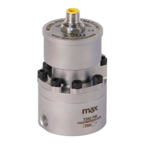
Positive displacement piston flow meter

Advertisement

Quick Links

P-Series User Manual
Positive Displacement Piston Flow Meters
P001HS
P001LA
P002
P213
P214
P215

Advertisement

Table of Contents
loading

Summary of Contents for Max P Series

  • Page 1 P-Series User Manual Positive Displacement Piston Flow Meters P001HS P001LA P002 P213 P214 P215...
  • Page 2 Never steam clean the meter. Damage will occur. (Bypass or remove the meter if necessary). Do not run water or aqueous solutions not approved by Max through your flow meter. Damage will occur. Do not disassemble the meter. Damage may occur. No serviceable parts inside.
  • Page 3: Table Of Contents

    Troubleshooting and Service Request ...........35 Additional Information Available .............35 Max Machinery, Inc. (MMI) reserves the right to change product specifications without notice to improve performance, reliability, or manufacturability. MMI shall not be held liable for operational, technical, or editorial errors/omissions. Visit our web site for the latest version of this user manual.
  • Page 4: How It Works

    How It Works Max P-Series Precision Flow Meters are positive displacement piston meters that are able to operate over a wide range of flow rates and fluid viscosities. High accuracy measurement is achieved through precision machined radial pistons that move proportional to the flow. High resolution outputs are produced by measuring the direction and speed of the pistons and converting the signals to analog or frequency outputs.
  • Page 5: Installation Mechanical

    Installation - Mechanical Your Max Flow Meter has been configured at the factory to be used out of the box based on your submitted application data. Plumb it, wire it, and use it. The following section will provide instructions on how to properly plumb your Max Flow Meter in the liquid lines of your application.
  • Page 6 Clean Plumbing: Before installing the flow meter, the system lines shall be cleaned and free of all debris or manufacturing particulates. Purging lines with compressed air or steam are typical cleaning methods. Do not use compressed air or steam on the Max flow meter, damage will occur. RADIATE HEAT HERE...
  • Page 7: Mechanical Operation

    Mechanical - Operation Determine that the following parameters of your flow metering system are within the specifications for the specific meter being used: Maximum System Pressure (Specifications) Differential Pressure across meter (Pressure Drop Curves) Maximum Flow Rate (Pressure Drop Curves) Metered Fluid Temperature (Sales specification, transmitter specifications page 8) If the metered fluid is greater than 28°C (80°F) over ambient, see the “High Temperature Start Up”...
  • Page 8: Installation Electrical

    Plumb it, wire it, and use it. The following section describes how to properly wire your Max Flow Meter into your application electronics. There are various combinations of transmitter components and outputs. These options include:...
  • Page 9: Electrical Quick Start

    Start-up Instructions - Adjustments to Factory Settings Required If you need to make adjustments to your Max Flow Meter prior to use, you will need to purchase and use the Max Machinery Interface Software Kit (SFT-KIT-001). This will allow you to change the flow meter output signal frequency or analog range to meet your application equipment needs.
  • Page 10 Electrical Installation Instructions - 5-pin Turck Connectors Applies only to transmitters with 5-pin, M12 style connectors. For hazardous location transmitters with 1/2 inch conduit connections, please refer to the EXInstall sheet. Frequency Output Transmitters (PN ending N/-) Turck® Connector Mating Cable Pin # Wire Color Label...
  • Page 11 Electrical - Operating Information Max Flow Meters require a fully isolated power supply to operate. Refer to the Max Machinery Interface Software Kit Manual for instructions on how to change the flow meter output signal frequency or analog range to meet your application’s equipment needs.
  • Page 12 LED Rotation/Output Indicators All Max transmitters incorporate an alternating red/green or blue/green LED to indicate magnet rotation in the meter. The color changes each 1/2 revolution of the meter. Additionally, when no flow signal is present, a rapidly flashing red...
  • Page 13: Field Compensation Of Transmitter

    An alternating blue/green LED indicates that the circuit is detecting a magnet and provides an output signal. A steady or flashing red LED indicates a problem with the transmitter PCA. Contact Max Machinery to have your flow meter refurbished.
  • Page 14 The flow meter being compensated must not be used for system flow rate feedback control during this process. The transmitter output is disabled during the compensation routine. If you are unable to run a stable flow in the field, send your meter in to Max Machinery for calibration. The compensation routine is as follows: 1.
  • Page 15: Led Functions

    5 revolutions at the stated flow rates. If compensation fails, restart the compensation process. When using the Interface Software Kit, follow instructions provided to correct errors prior to attempting compensation again. If problems persist, contact Max Machinery at 707-433-2662 or at www.maxmachinery.com.
  • Page 16: Specifications

    Optional: Perfluoroelastmer FREQUENCY TRANSMITTER Output Signal Standard: 5 Vdc, single phase Optional: Quadrature 5 Vdc, two phase Current sinking, 20 mA max., single phase K-Factor Single Phase: 12,000 pulses/cc Two Phase: 24,000 pulses/cc, 4x decoded (6,000 pulses/cc/phase, 1x decoded) Power Supply Requirements...
  • Page 17 Optional: Perfluoroelastmer FREQUENCY TRANSMITTER Output Signal Standard: 5 Vdc, single phase Optional: Quadrature 5 Vdc, two phase Current sinking, 20 mA max., single phase K-Factor Single Phase: 12,000 pulses/cc Two Phase: 24,000 pulses/cc, 4x decoded (6,000 pulses/cc/phase, 1x decoded) Power Supply Requirements...
  • Page 18 Optional: Perfluoroelastmer FREQUENCY TRANSMITTER Output Signal Standard: 5 Vdc, single phase Optional: Quadrature 5 Vdc, two phase Current sinking, 20 mA max., single phase K-Factor Single Phase: 1,000 pulses/cc Two Phase: 2,000 pulses/cc, 4x decoded (500 pulses/cc/phase, 1x decoded) Power Supply Requirements...
  • Page 19 Optional: Teflon®, Perfluoroelastmer, Neoprene FREQUENCY TRANSMITTER Output Signal Standard: 5 Vdc, single phase Optional: Quadrature 5 Vdc, two phase Current sinking, 20 mA max., single phase K-Factor Single Phase: 1,000 pulses/cc Two Phase: 2,000 pulses/cc, 4x decoded (500 pulses/cc/phase, 1x decoded)
  • Page 20 Optional: Teflon®, Perfluoroelastmer, Neoprene FREQUENCY TRANSMITTER Output Signal Standard: 5 Vdc, single phase Optional: Quadrature 5 Vdc, two phase Current sinking, 20 mA max., single phase K-Factor Single Phase: 90 pulses/cc Two Phase: 180 pulses/cc, 4x decoded (45 pulses/cc/phase, 1x decoded)
  • Page 21 Optional: Teflon®, Perfluoroelastmer, Neoprene FREQUENCY TRANSMITTER Output Signal Standard: 5 Vdc, single phase Optional: Quadrature 5 Vdc, two phase Current sinking, 20 mA max., single phase K-Factor Single Phase: 20,000 pulses/L Two Phase: 40,000 pulses/L, 4x decoded (10,000 pulses/L/phase, 1x decoded)
  • Page 22: Dimensions

    Dimensions P001LA SPECIFICATIONS EX-PROOF HOUSING TOP VIEW MODEL P001LA WITH TUBE PORT AND INDUSTRIAL HOUSING MODEL P001LA WITH TUBE PORT BOTTOM VIEW AND EX-PROOF HOUSING P-Series User Manual Rev2022...
  • Page 23 Dimensions P001 SPECIFICATIONS EX-PROOF HOUSING TOP VIEW MODEL P001 WITH TUBE PORT AND INDUSTRIAL HOUSING BOTTOM VIEW MODEL P001 WITH TUBE PORT AND EX-PROOF HOUSING P-Series User Manual Rev2022...
  • Page 24 Dimensions P002 SPECIFICATIONS EX-PROOF HOUSING TOP VIEW MODEL P002 WITH SAE PORT AND INDUSTRIAL HOUSING MODEL P002 WITH SAE PORT AND EX-PROOF HOUSING BOTTOM VIEW P-Series User Manual Rev2022...
  • Page 25 Dimensions P213 SPECIFICATIONS EX-PROOF HOUSING TOP VIEW MODEL P213 WITH NPT PORT AND INDUSTRIAL HOUSING BOTTOM VIEW MODEL P213 WITH NPT PORT AND EX-PROOF HOUSING P-Series User Manual Rev2022...
  • Page 26 Dimensions P213 SPECIFICATIONS EX-PROOF HOUSING TOP VIEW MODEL P213 WITH SAE PORT AND INDUSTRIAL HOUSING BOTTOM VIEW MODEL P213 WITH SAE PORT AND EX-PROOF HOUSING P-Series User Manual Rev2022...
  • Page 27 Dimensions P213 SPECIFICATIONS EX-PROOF HOUSING TOP VIEW MODEL P213 WITH MANIFOLD PORT AND INDUSTRIAL HOUSING BOTTOM VIEW MODEL P213 WITH MANIFOLD PORT AND EX-PROOF HOUSING P-Series User Manual Rev2022...
  • Page 28 Dimensions P214 SPECIFICATIONS EX-PROOF HOUSING TOP VIEW MODEL 214 WITH INDUSTRIAL HOUSING TRANSMITTER BOTTOM VIEW MODEL 214 WITH EX-PROOF HOUSING TRANSMITTER P-Series User Manual Rev2022...
  • Page 29 Dimensions P214 SPECIFICATIONS EX-PROOF HOUSING TOP VIEW MODEL 214 WITH INDUSTRIAL HOUSING TRANSMITTER MODEL 214 WITH EX-PROOF BOTTOM VIEW HOUSING TRANSMITTER P-Series User Manual Rev2022...
  • Page 30 Dimensions P215 SPECIFICATIONS EX-PROOF HOUSING TOP VIEW MODEL 215 WITH INDUSTRIAL HOUSING TRANSMITTER BOTTOM VIEW MODEL 215 WITH EX-PROOF HOUSING TRANSMITTER P-Series User Manual Rev2022...
  • Page 31 Dimensions REMOTE PCA ENCLOSURE SPECIFICATIONS REMOTE PCA ENCLOSURE FOR HIGH TEMPERATURE TRANSMITTERS (Not Shown: Industrial 2 meter interconnect cable included, Ex-Proof user supplied interconnect cable required) P-Series User Manual Rev2022...
  • Page 32: Charts

    Charts P001LA Pressure Drop Graph P001 Pressure Drop Graph P002 Pressure Drop Graph P-Series User Manual Rev2022...
  • Page 33 Charts P213 Pressure Drop Graph P214 Pressure Drop Graph P215 Pressure Drop Graph P-Series User Manual Rev2022...
  • Page 34 Flow Meter Selections Transmitter Selections Model # Non-Standard Options Bi-Directional Cal: BID Transmitter Type Max Flow Range Output Type 0.2 Liters/Min P001 4-20mA Output - Powered by 24 Vdc 4-20mA Output - Powered by 12 Vdc 0-10 Volt Output - Powered by 24 Vdc 0-10 Volt Output - Powered by 12 Vdc 5V Pulse/Freq.
  • Page 35 Piston Type, P-Series 3000 psi (210 bar) rated Flow Meter Selections Transmitter Selections Model # Non-Standard Options Bi-Directional Cal: BID 0 Transmitter Type Max Flow Range Output Type 1.8 Liters/Min P213 4-20mA Output - Powered by 24 Vdc 10 Liters/Min P214...
  • Page 36 Piston Type, P-Series 7250 psi (500 bar) rated Flow Meter Selections Transmitter Selections Model # Non-Standard Options Bi-Directional Cal: BID Transmitter Type Max Flow Range Output Type 0.2 Liters/Min P001 4-20mA Output - Powered by 24 Vdc 2 Liters/Min P002...
  • Page 37: Available Accessories

    Available Accessories Accessories to support your system and simplify your installation and maintenance are available direct from Max. Request yours when you order your flow meter. See the website for information and options. Interface Software Kit Part # Description SFT-KIT-001 USB drive transmitter programming software and serial cable.
  • Page 38: Troubleshooting And Service Request

    Additional information about our products, including STEP files and Sample Calibration sheets, may be found on our website at https://www.maxmachinery.com/downloads/. MMI products are covered under our standard manufacturer’s warranty. Details may be found at https://www.maxmachinery.com/warranty/. Max Machinery, Inc., 33A Healdsburg Avenue, Healdsburg, CA 95448 USA 707.433.2662 | www.maxmachinery.com P-Series User Manual Rev2022...

This manual is also suitable for:

P001hsP001laP002P213P214P215

Table of Contents