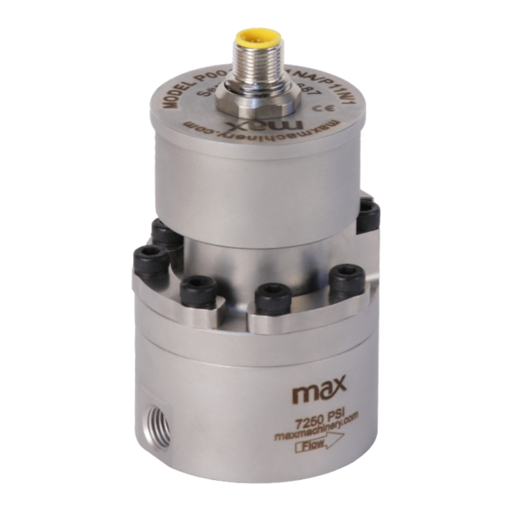
Summarization of Contents
Safety and Precautions
General Safety Precautions
Crucial safety warnings for operating and handling Max flow meters to prevent damage or injury.
Installation - Mechanical
Mounting Orientation
Recommended meter orientations for optimal air purging and heat management.
NPT Fitting Installation
Procedures for installing NPT fittings using pipe sealant or tape correctly.
SAE/BSPP Fitting Installation
Guidelines for attaching SAE/BSPP fittings using appropriate O-ring lubricant.
Compression Fitting Installation
Steps for installing compression fittings, including ferrule usage and torque.
Mechanical Installation Procedures
Bypass Valve Installation
Installing bypass valves to facilitate system start-up and maintenance.
Filtration Recommendations
Recommended filter micron ratings for different P-Series flow meter models.
Clean Plumbing Guidelines
Best practices for cleaning system lines before flow meter installation.
High Temperature Installation
Techniques for orienting and insulating meters for high-temperature operation.
Mechanical - Operation
High Temperature Start Up
Procedure to prevent thermal shock for fluids above 82°C (150°F).
Electrical Installation - Quick Start & Adjustments
Quick Start - Factory Settings
Connecting flow meters to automation systems without initial adjustments.
Start-up Adjustments to Factory Settings
Using software for adjusting output signal frequency or analog range.
5-pin Turck Connector Wiring
Frequency Output Transmitter Wiring
Wiring diagram and pinout for frequency output transmitters.
Analog Output Transmitter Wiring
Wiring diagram and pinout for analog output transmitters.
Electrical - Operating Information
Transmitter Removal and Installation
Procedures for removing and reattaching industrial transmitters correctly.
Moisture Seal Protection
Importance of O-ring seals for maintaining the transmitter enclosure's integrity.
Environmental Temperature Ratings
Fluid and ambient temperature limits for industrial transmitter housings.
High Temperature and Troubleshooting
High Temperature Operation Guidance
Orienting and insulating meters for optimal performance in high temperatures.
LED Troubleshooting Indicators
Interpreting LED colors and flash patterns to diagnose errors.
Field Compensation of Transmitter
Accessing PCA Button and Serial Port
Steps to access the transmitter's PCA button and software serial port for compensation.
Field Compensation Procedures
Compensation Routine Steps
Step-by-step guide to performing field compensation for transmitter PCA.
LED Functions
Normal Operation LED Status
LED indications for normal functioning and no-flow states.
Compensation Status LED
LED indications for successful or failed compensation attempts.
Specifications Overview
P001LA Model Specifications
Detailed specifications for the P001LA flow meter model.
Frequency Transmitter Specifications
Technical details for the frequency output transmitter.
Analog Transmitter Specifications
Technical details for the analog output transmitter.
Specifications (P001)
P001 Model Specifications
Detailed specifications for the P001 flow meter model.
Specifications (P002)
P002 Model Specifications
Detailed specifications for the P002 flow meter model.
Specifications (P213)
P213 Model Specifications
Detailed specifications for the P213 flow meter model.
Specifications (P214)
P214 Model Specifications
Detailed specifications for the P214 flow meter model.
Specifications (P215)
P215 Model Specifications
Detailed specifications for the P215 flow meter model.
Dimensions
P001LA Dimensions
Visual representation of P001LA flow meter with key dimensions.
Dimensions (P001)
P001 Dimensions
Visual representation of P001 flow meter with key dimensions.
Dimensions (P002)
P002 Dimensions
Visual representation of P002 flow meter with key dimensions.
Dimensions (P213 NPT)
P213 NPT Port Dimensions
Dimensions for P213 flow meter with NPT port.
Dimensions (P213 SAE)
P213 SAE Port Dimensions
Dimensions for P213 flow meter with SAE port.
Dimensions (P213 Manifold)
P213 Manifold Port Dimensions
Dimensions for P213 flow meter with manifold port.
Dimensions (P214 Industrial)
P214 Industrial Housing Dimensions
Dimensions for P214 flow meter with industrial housing.
Dimensions (P214 Ex-Proof)
P214 Ex-Proof Housing Dimensions
Dimensions for P214 flow meter with ex-proof housing.
Dimensions (P215)
P215 Dimensions
Visual representation of P215 flow meter with key dimensions.
Dimensions (Remote PCA)
Remote PCA Enclosure Dimensions
Key dimensions for the remote PCA enclosure.
Charts
P001LA Pressure Drop Graph
Graph showing pressure drop vs flow rate for P001LA at various viscosities.
P001 Pressure Drop Graph
Graph showing pressure drop vs flow rate for P001 at various viscosities.
P002 Pressure Drop Graph
Graph showing pressure drop vs flow rate for P002 at various viscosities.
Charts (Continued)
P213 Pressure Drop Graph
Graph showing pressure drop vs flow rate for P213 at various viscosities.
P214 Pressure Drop Graph
Graph showing pressure drop vs flow rate for P214 at various viscosities.
P215 Pressure Drop Graph
Graph showing pressure drop vs flow rate for P215 at various viscosities.
Model Selection and Specifications (250 psi)
P001LA Model Number Breakdown
Explanation of P001LA model number coding for selections.
Output Type Options
Available output types for the transmitter (e.g., 4-20mA, 5V Pulse).
Temperature Rating Options
Available temperature ratings for the transmitter housing.
Model Selection and Specifications (3000 psi)
P213 Model Number Breakdown
Explanation of P213 model number coding for selections.
Fluid Connection Options
Available fluid connection types (NPT, SAE, Manifold).
Seal Selection Options
Available seal material options for the flow meter.
Model Selection and Specifications (7250 psi)
P001 Model Number Breakdown
Explanation of P001 model number coding for selections.
Electrical Connection Options
Available electrical connection types (Industrial, Hazardous Location).
Signal Type Options
Available signal types (Pulse, Analog, Quadrature).
Available Accessories
Interface Software Kit
USB programming software and serial cable for transmitter adjustments.
Cables
Turck to wire cables in various lengths for transmitter connection.
Rate Indicator/Totalizers
Panel mount indicator for displaying flow rate and total.
Filters and Filter Element Kits
Inline filters and replacement elements with various micron ratings.
PCA Replacement Kits
Replacement kits for the transmitter's Printed Circuit Assembly.
Troubleshooting and Service Request
No Flow or High Pressure Drop
Corrective actions for issues like blockage or meter failure.
Fluid Flow No Indication
Troubleshooting steps for incorrect wiring or meter not turning.
Flow Indication Discrepancies
Addressing issues like air in line, calibration, or reverse flow.
Additional Information and Support
Resources for refurbishment, calibration, downloads, and warranty.


Need help?
Do you have a question about the P214 and is the answer not in the manual?
Questions and answers