
Related Manuals for Max G Series


Summary of Contents for Max G Series
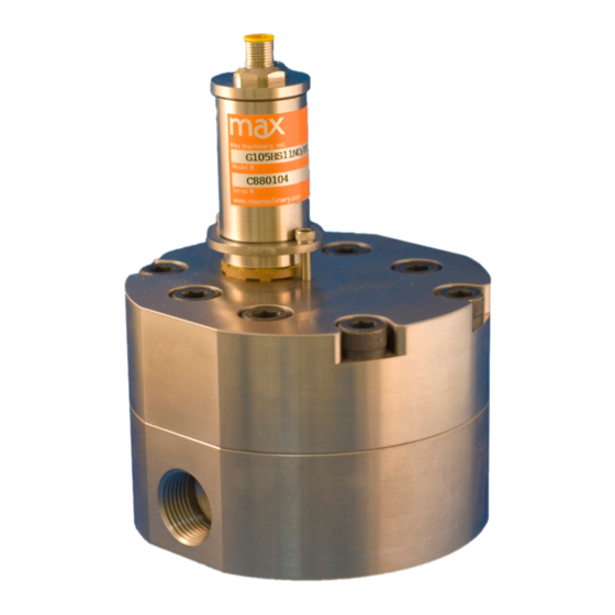
- Page 1 G series Flow Metering Systems Operational Manual For Models G004 thru G240 This manual is for the Max 260 series of gear flow meters and the integrated model 269 solid state transmitter...
- Page 2 Additional technical documents regarding transmitter performance and advanced operation are available at: http://www.maxmachinery.com/ Max Machinery, Inc. reserves the right to make changes to the product in this instruction manual to improve performance, reliability, or manufacturability. Contact Max Machinery Inc. for the latest available specifications and performance data.
-
Page 3: General Description
Solid state sensors are used to detect the position of a driven magnet inside the Max flow meter. Changes in position are tracked by a microprocessor, which generates an output frequency proportional to the flow rate. Advanced signal processing provides both fine angular resolution (0.36 degrees rotation per pulse) and rapid response (output updated every 1 ms). -
Page 4: Installation
Installation - Flow Meter Prior to installing the flow meter remove the storage caps from the ports and look carefully into each port of the meter. Ensure that no dirt or foreign particles have gotten into the ports of the meter. Make sure that adequate filtration exists upstream of the flow meter and that no contaminants exist in the line between the filter and flow meter. -
Page 5: High Temperature Operation
Installation -Transmitter Mechanical Transmitters are installed on the meter at the factory. If a transmitter needs to be replaced in the field, use the following procedure: 1. Disconnect wiring and remove the two socket cap screws to remove old transmitter. 2. - Page 6 DO: Install proper filtration immediately upstream of the flow meter. DON’T: Run water or aqueous solutions not approved by MAX through your flow meter as it DO: Install the meter in the pressurized/ may cause internal galling. upstream section of the circuit if the working fluid is prone to cavitation (thin fluids or low DON’T: Steam clean the meter (bypass or...
- Page 7 Repairs The Max G-Series Meters are not designed for user repair and all such work should be done at the factory or under the direct supervision of the Max Technical Service Department. Unauthorized repair work may damage the meter and will void the product warranty. Please make note of model and serial numbers on the flow meter before calling the factory.
-
Page 8: Specifications
Flow meter Specifications Model # G004 G015 G045 G105 G240 Max Flow (1) 4 LPM 15 LPM 45 LPM 105 LPM 240 LPM (1GPM) (4 GPM) (11.9 GPM) (28 GPM) (64 GPM) Operating 425 bar 425 bar 425 bar 425 bar... - Page 9 100 Ω Output Impedance Rise/Fall Time 0.2 μ Sec Output Update Rate(2) 1 ms Min/Max Frequency 0-60 kHz Resolution 1 - 1000 pulses/rev Ambient Temperature Range Transmitter (Storage) –40ºC to 85ºC (–40ºF to 185ºF) Transmitter (Operation) (3) –40ºC to 80ºC (–40ºF to 175ºF)
- Page 10 Flow Measurement Stability: The Max G Series meter family utilizes a sensitive measurement circuit that tracks the meter rotation to within a fraction of a degree of rotation. This gives extremely responsive measurement of flow changes combined with excellent measurement of very low flows. This same high resolution can lead to an increased sensitivity to signal noise.
Need help?
Do you have a question about the G Series and is the answer not in the manual?
Questions and answers