Advertisement
MAINS SETTING (Run mode)
VENTILATION TEMPERATURE SETTING

Press °C VENT :
This message will be displayed instead of the
°Set Ventilation temperature value (start first ventilation).
Press + or - to modify, press °C VENT to confirm.

MINIMUM SPEED SETTING

Press MIN VENT:
This message will be displayed instead of the Minimum Ventilation.
Press + or - to modify, press MIN to confirm.


If the minum speed is set 0 , this message appears instead of the Set partialized On time in seconds.
Press + or - to modify, press MIN to confirm.


At this point, this message appears instead of the Set partialized Of time in seconds.
Press + or - to modify, press MIN to confirm.

MAXIMUM SPEED SETTING.

Press MAX VENT:
This message will be displayed instead of the Maximum Ventilation.
Press + or - to modify, press MAX to confirm.

VIEWING AMBIENT TEMPERATURE RECORDING

Press +: 
will be displayed followed by °Maximum Temperature Recording.
Press -: 
will be displayed followed by °Minimum Temperature Recording.
Values are permanently stored in the memory: for deleting all values in the memory keep pushed + key for more than 3 seconds: CLEA message will appear on display before clearing operation.
COSt PROGRAMMING (System constants)

These settings refer to the operation mode of the system and must be made on initial startup. Press - / + at the same time for at least one second: the message C.O.S.t. will be displayed.

Press than repeatedly MAX VENT until the message regarding the chosen variable is displayed (see table below): value of variable and message will be displayed.
Press + or - to set a new value and then press MAX VENT to confirm.
The next system constant will then appear.
You can press MAX VENT for at least 2 seconds to exit and return to the Run Mode.
| Mess. | Value | Meaning | Note |
| r.1 | 0.0 ° | ° Start ventilation 1 reffering to °VEnt setting | *1) |
| r.2 | 1.0 ° | ° Start ventilation 2 reffering to start ventilation 1 | *1) |
| r.3 | 1.0 ° | ° Start ventilation 3 reffering to start ventilation 2 | *1) |
| r.4 | 1.0 ° | ° Start ventilation 4 reffering to start ventilation 3 | *1) |
| d. FAn | 0.2 ° | ° Ventilation differential | *1) |
| dEL.F | 1" | Ventilation step on delay seconds | |
| r. HEA | -0.5 ° | ° HEAT setting referring to °C VENT | *2) |
| d. HEA | 0.2 ° | ° HEAT differential | *3) |
| tEnP | =1 | Temperature representation | *4) |
| Ad.tE | 0.0 ° | ° input sensor temperature correction | *5) |
*1) For more details see Operative diagram.
*2) This set is a relative set reffered to temperature setted on°C VENT key.
For example if is setted °C VENT=25.0° and r. HEA=-0.5° heating command (HEAT) will start at 24.5° (25.0°-0.5°). Heating will be OFF after 0.2° (value d. HEA).
*3) tEnP =0 ; °C Temperature range.
tEnP =1 ; °F Temperature range.
*4) You can correct the readings on the sensor (+ or -).
PRESET PROGRAMS

This processor is already programmed with the following (variable) settings.
To return to these settings at any time you may:
Power off the processor, press MAX VENT key and keep it pressed giving power on: boot message will be displayed (release now MAX VENT key).
t. FAn= 25.0° SP_ _ =0 -on- =0" -oF- = 0" SP - - =4
The COSt values are shown in COSt Promagramming.
MANUAL MODE

In some start-up conditions may be useful to work in "manual" mode:
Power off the processor, press + key and keep it pressed giving power on: HAnd message will be displayed (release now + key).
Push + until is displayed number required to be handed (see Status indication lamp) and push MAX VENT for activing relay.
Pushing again + for increase relay number previous relay is disactivated.
You can press MAX VENT key for a least two seconds to escape and return to the Run Mode.
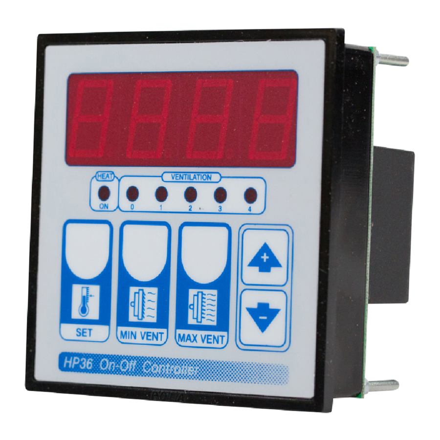
STATUS INDICATION LAMPS
The light situated at the bottom of the display shows the state of the controller:

| Lamp. | State | N° Relay | Contacts |
| HEAT | HEAT ON | 5 | 11-12-13 |
| VENT 1 | VENT. 1 ON | 1 | 3-4 |
| VENT 2 | VENT. 2 ON | 2 | 3-5 |
| VENT 3 | VENT. 3 ON | 3 | 3-6 |
| VENT 4 | VENT. 4 ON | 4 | 3-7 |
OPERATING DIAGRAM

INSTALLATION
How to connect the sensors
Connect the provided sensor as shown in the diagram. For remote connections use a standard 0.5-square millimeter two-pole wire, taking great care over the connections, by insulating and sealing the joins carefully. -O.C.- is displayed when the temperature sensor wiring is open, -S.C.- is displayed when the temperature sensor wiring is short circuit.
How to connect the line
Connect line on terminals L-N.
Protect supply with adequate fuse.
How to connect the contacts
Connect terminals 3-7 / ...11-13 on the terminal block (contacts up to 4AMP.AC1).
Ventilator's contacts are progressive type.
Output contacts are N.O. (Normally Opened and free of voltage) on wich is aplliable a 4AMP AC1 maximum load.
3-4= VENT 1 contact.
3-5= VENT 2 contact.
3-6= VENT 3 contatc.
3-7= VENT 4 contact.
11-12= Heat contact.
12-13= Cool contact.

* Other power voltage if you required

As it company policy to continually improve the products the Manufacturers reserve the right to make any modifications thereto without prior notice. They cannot be held liable for any damage due to malfunction.

Documents / ResourcesDownload manual
Here you can download full pdf version of manual, it may contain additional safety instructions, warranty information, FCC rules, etc.
Download POLA HP36 - On-off Ventilation Controller Instructions
Advertisement


Need help?
Do you have a question about the HP36 and is the answer not in the manual?
Questions and answers