Table of Contents
Advertisement
Quick Links
Advertisement
Table of Contents
Troubleshooting

Related Manuals for Jasic EVO 2.0 EP-45


Summary of Contents for Jasic EVO 2.0 EP-45
- Page 1 ClearVision (Optional TFT-LCD screen included)
-
Page 2: Your New Product
Please ensure that you carry out daily and periodic maintenance checks to ensure years of reliable and trouble free operation. Please call your Jasic distributor in the unlikely event of a problem occurring. Please record below the details from your product as these will be required for warranty purposes and to ensure you get the correct information should you require assistance or spare parts. -
Page 3: Table Of Contents
General Cutting Information Cut Quality Troubleshooting Troubleshooting - Error Codes Troubleshooting - Plasma Cutting Problems Maintenance Options and Accessories WEEE Disposal RoHS Compliance Declaration UKCA Declaration of Conformity EC Declaration of Conformity Statement of Warranty Schematics Notes Jasic Contact Details... -
Page 4: Safety Instruction
SAFETY INSTRUCTIONS These general safety norms cover both arc welding machines and plasma cutting machines unless otherwise noted. The user is responsible for installing and operating the equipment in accordance with the enclosed instructions. It is important that users of this equipment protect themselves and others from harm, or even death. The equipment must only be used for the purpose it was designed for. -
Page 5: Ppe
SAFETY INSTRUCTION Use of Personal Protective Equipment (PPE) Welding arc rays from all welding and cutting processes can produce intense, visible and invisible (ultraviolet and infrared) rays that can burn eyes and skin. • Wear an approved welding helmet fitted with an appropriate shade of filter lens to protect your face and eyes when welding, cutting or watching. -
Page 6: Fume And Welding Gases
SAFETY INSTRUCTION Safety against fumes and welding gases The HSE have identified welders as being an ‘at risk’ group for occupational diseases arising from exposure to dusts, gases, vapours and welding fumes. The main identified health effects are pneumonia, asthma, chronic obstructive pulmonary disease (COPD), lung and kidney cancer, metal fume fever (MFF) and lung function changes. -
Page 7: The Working Environment
SAFETY INSTRUCTION The working environment Ensure the machine is mounted in a safe and stable position allowing for cooling air circulation. Do not operate equipment in an environment outside the laid down operating parameters. The welding power source is not suitable for use in rain or snow. Always store the machine in a clean, dry space. -
Page 8: Rf Declaration
SAFETY INSTRUCTIONS Fire awareness The cutting and welding process can cause serious risks of fire or explosion. Cutting or welding sealed containers, tanks, drums or pipes can cause explosions. Sparks from the welding or cutting process can cause fires and burns. Check and risk assess the area is safe before doing any cutting or welding. -
Page 9: Materials And Their Disposal
For more detailed information please refer to the HSE website www.hse.gov.uk PACKAGE CONTENTS AND UNPACKING Supplied within your new Jasic EVO product package will be the following items with each model. Use care when unpacking the contents and ensure all items are present and not damaged. -
Page 10: Description Of Symbols
DESCRIPTION OF SYMBOLS Read this operation manual carefully before use. Warning in operation. Single-phase static frequency converter-transformer rectifier. Symbol of single-phase AC power supply and rated frequency. Can be used in the environment which has high risk of electric shock. Degree of protection, such as IP23S. -
Page 11: What Is Plasma
WHAT IS PLASMA? • Plasma is commonly described as the fourth state of matter (i.e. solid, liquid, gas then plasma). • If you increase gas to an extremely high temperature you get the fourth state plasma, the energy begins to break apart the gas molecules and the atoms begin to split. -
Page 12: Product Overview
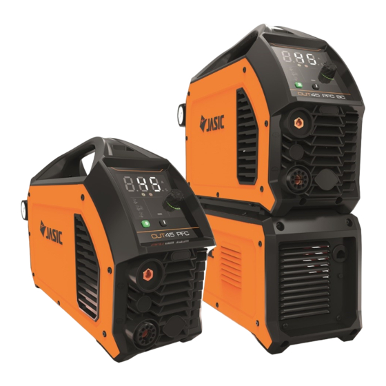
PRODUCT OVERVIEW The Jasic EVO plasma cutting inverter range of machines have been designed as portable cutting power supplies incorporating the most advanced inverter, offering excellent performance. The EVO Plasma machines generate a stable DC arc that will easily cut through carbon steel, low alloy steel, stainless steel and other materials. -
Page 13: Technical Specifications
TECHNICAL SPECIFICATIONS Parameter Unit Jasic Arc EP-45 PFC Jasic Arc EP-45SC PFC Rated input (U1) V & Hz AC 95 ~ 265V 50/60 AC 95 ~ 265V 50/60 115V - 20 115V - 26 Rated input current (Ieff) 230V - 11.5... -
Page 14: Description Of Ep-45 (Clearvision Control Panel)
12. Input air regulator - Compressed air inlet 13. Machines ON/OFF power switch 14. Rear panel with integrated cooling vents 15. Input power cable Control panel view Jasic Cut EP-45 16. Parameter and error code display area 17. Warning indicators 18. Cutting mode selection area and selector button 19. - Page 15 DESCRIPTION OF (CLEARVISION CONTROL PANEL) A. Current, parameter and error code display area B. Warning indicators C. Parameter adjustment knob and button D. Cutting mode selection options E. Cutting mode selection button F. Gas test check button with indicator above A.
- Page 16 DESCRIPTION OF ‘CLEARVISION’ CONTROL PANEL Engineer mode 1. Press and hold the parameter adjustment knob for 5 seconds when not cutting to enter engineers mode. 2. After pressing for 1 second, the display window will count down from 3, then the machine will enter engineer mode.
-
Page 17: Description Of Ep-45 (Optional Tft-Lcd Control Panel)
14. Rear panel with integrated cooling vents 15. Input power cable Control panel view Jasic Cut EP-45 16. Home Button: Pressing this button will take you directly to the home screen (as shown) 17. The parameter control dial is also a control button which when pressed ‘confirms’... - Page 18 DESCRIPTION OF ‘TFT-LCD’ CONTROL PANEL Display screen The display screen offers the operator a wealth of information including operation mode, parameters that include, cutting current, post-flow time and post-flow gas. The home screen is shown right and using the adjustment dial allows you to navigate through the machines options.
- Page 19 DESCRIPTION OF ‘TFT-LCD’ CONTROL PANEL Display screen options Cutting current configuration Whether you access either continuous or mesh cutting mode the display window will show the cutting current (as shown right). By rotating the control dial you will adjust the cutting current value.
- Page 20 DESCRIPTION OF ‘TFT-LCD’ CONTROL PANEL Display screen options Gas Check Function When not cutting in either ‘Continuous Cut’ or ‘Mesh Cut’ you can activate the gas to check your gas flow by selecting the gas check function, highlighted in green below. If the gas check symbol is shown, as above right shows, you now have air flowing though the plasma torch which indicates that the machine is now in ‘Gas Check’...
- Page 21 DESCRIPTION OF ‘TFT-LCD’ CONTROL PANEL Display screen options Language Selection (continued) From the language screen, you can rotate the control dial to scroll through the installed language options and select your choice by pressing the control dial button. Press the return button or home button to exit Unit Configuration From the settings screen, rotate the control dial to select the ‘unit ’...
- Page 22 DESCRIPTION OF ‘TFT-LCD’ CONTROL PANEL Display screen options Overvoltage protection option From the configuration screen, rotate the control dial until the ‘Overvoltage Protection Switch’ option is highlighted and press the control dial. You can now select either ON (open/enabled) or OFF (close/ disabled) as shown below.
- Page 23 DESCRIPTION OF ‘TFT-LCD’ CONTROL PANEL Display screen options User manual In the ‘Home page’, rotate the control dial to the ‘user manual’ tab and then press the control dial. You have now opened the user manual option screen as shown below where you have easy access to some of the machines user instructions.
-
Page 24: Description Of Air Compressor
Net weight 17.15 Overall weight 18.40 Front view Jasic EP-SC air compressor 1. Front panel with integrated cooling vents 2. Input power indicator light 3. Input power cable and 4 pin control plug which connects to the power source front panel matching 4 pin socket Rear view Jasic EP-SC air compressor 4. -
Page 25: Installation
Carefully remove the machine and retain the packaging or at least until the installation is complete. Lifting The Jasic EP-45 range do have an integrated handle for hand lifting only. Please ensure the machine unit is lifted and transported safely and securely. Location The machine should be located in a suitable position and environment. - Page 26 Input air connection • The Jasic EVO EP-45 and EP-45SC Plasma machines are only designed to be used with a reliable, consistent supply of clean, dry compressed air which is essential for correct operation. The EP-45SC version can utilizes its own ‘internal’ compressed air supply system.
-
Page 27: User Set-Up
Fitting the supplied plasma torch On the Jasic EVO range of plasma machines, the plasma torch fitting instructions (shown below) need to be observed. ... - Page 28 USER SET UP Before starting any welding activity ensure that you have suitable eye protection and protective clothing. Also take the necessary steps to protect any personnel within the welding area. Please note: The following should only be carried out by the authorised operator. Air pressure setting The external air pressure regulator is mounted on the machines rear panel and is only present and used when workshop compressed air is connected.
-
Page 29: Operation
OPERATION Before starting any welding or cutting activity ensure that you have suitable eye protection and protective clothing. Also take the necessary steps to protect any persons within the welding area. Plasma cutting Check that all connections have been made as required. Check the following before starting the machine. •... - Page 30 OPERATION Before starting any welding activity ensure that you have suitable eye protection and protective clothing. Also take the necessary steps to protect any personnel within the welding area. Operation continued Normal cutting mode Normal cutting - this mode is the most commonly used for edge start or pierce cutting. When edge cutting, hold the torch perpendicular to the edge of the material being cut with the cutting tip near (but not touching) the edge of the workpiece at the point where the cut is to start.
-
Page 31: Operation - Modes Of Cutting
OPERATION - MODES OF CUTTING Before starting any welding activity ensure that you have suitable eye protection and protective clothing. Also take the necessary steps to protect any personnel within the welding area. Modes of cutting The following pages show various ways by using different consumable configurations that allows the operator to cut material with the plasma torch. - Page 32 OPERATION - MODES OF CUTTING Before starting any welding activity ensure that you have suitable eye protection and protective clothing. Also take the necessary steps to protect any personnel within the welding area. Modes of cutting The images below show two different ways by using different consumable configurations that allows the operator to cut material with the plasma torch.
- Page 33 OPERATION - MODES OF CUTTING Before starting any welding activity ensure that you have suitable eye protection and protective clothing. Also take the necessary steps to protect any personnel within the welding area. Modes of cutting Piercing When not starting your cut from the material edge, most likely you will be piercing the material when starting the cut which is the process in which a quick hole is made in the work piece.
-
Page 34: Plasma Torch Breakdown
Retaining Cap 60389C Shield Cup Body 60432 Double Pointed Spacer (for items 6 & 7 only) 60485 Shield Cap, Hand 09600.63 Wrench for Electrode Please Note: Configuration above only to be used on the Jasic Cut EP-45 and EP-45SC Plasma Machine... -
Page 35: General Cutting Information
GENERAL CUTTING INFORMATION Before starting any welding or cutting activity ensure that you have suitable eye protection and protective clothing. Also take the necessary steps to protect any persons within the welding area. Notes for cutting operation 1. Do not touch the hot work piece with bare hands to avoid burning. 2. -
Page 36: Cut Quality
If you plan to keep the piece from which the circle was cut from then move in an anti-clockwise direction. The Jasic EVO range of plasma machines offer optional circle cutting guide kits to assist with circle cutting. - Page 37 Speeds shown below are offered as a guide only for our Jasic hand cutting systems using compressed air, cutting mild steel material with the stated output currents ensuring that the cutting tip fitted matches the stated amperages.
-
Page 38: Troubleshooting
TROUBLESHOOTING The following operation requires sufficient professional knowledge on electric aspects and comprehensive safety knowledge. Make sure the input cable of the machine is disconnected from the electricity supply and wait for 5 minutes before removing the machine covers. Before any welding and cutting machines are dispatched from the factory, they have already been checked thoroughly. -
Page 39: Troubleshooting - Error Codes
The below is a list of error codes for the Jasic EVO EP-45 and EP-45SC plasma cutting machines. Error Code... -
Page 40: Troubleshooting - Plasma Cutting Problems
TROUBLESHOOTING - PLASMA CUTTING PROBLEMS The proper installation, application and operation of plasma arc cutting equipment can save many man hours and reduce costs which will give you the promised cut quality and longer consumable parts life. Cut quality issues or poor consumable life are generally the most experienced problems seen with plasma cutting systems and more often than not are caused by the same thing, for example, low or too high air pressure, low air flow, water or oil in the supply airline will all give you poor cut quality and premature consumable wear. -
Page 41: Maintenance
MAINTENANCE The following operation requires sufficient professional knowledge on electric aspects and comprehensive safety knowledge. Make sure the input cable of the machine is disconnected from the electricity supply and wait for 5 minutes before removing the machine covers. In order to guarantee that your cutting and welding machine works efficiently and in safety, it must be maintained regularly. -
Page 42: Options And Accessories
Part Number Description JE60-6 6m Plasma Torch EC-2-03LD Work Return Lead and Clamp 3m CP3550 Cable Plug 35-50mm JH-HDX Jasic HD True Colour Auto Darkening Welding Helmet TFT-EP-45P TFT-LCD ‘Advanced’ Control Panel Option 51866 Circle Cutting Guide Kit EP-SC Compressor unit... -
Page 43: Weee Disposal
Jasic has a relevant recycling system which is compliant and registered in the UK with the environment agency. Our registration reference is WEEMM3813AA. -
Page 44: Ukca Declaration Of Conformity
UKCA Declaration of Conformity... -
Page 45: Ec Declaration Of Conformity
EC DECLARATION OF CONFORMITY... -
Page 46: Statement Of Warranty
3 month warranty. Jasic shall in no event be responsible for any third party expenses or expenses/costs or any indirect or consequential expenses/costs. -
Page 47: Schematics
SCHEMATICS EP-45 * Please Note: Depending on region, torch socket and torch wiring maybe different. EP-45SC * Please Note: Depending on region, torch socket and torch wiring maybe different. Compressor 4 Pin Plug Pins function 1 - 2 115V AC 1 - 3 230V AC Ground... -
Page 48: Notes
NOTES _____________________________________ _____________________________________ _____________________________________ _____________________________________ _____________________________________ _____________________________________ _____________________________________ _____________________________________ _____________________________________ _____________________________________ _____________________________________ _____________________________________ _____________________________________ _____________________________________ _____________________________________ _____________________________________ _____________________________________ _____________________________________ _____________________________________ _____________________________________ _____________________________________... - Page 49 NOTES _____________________________________ _____________________________________ _____________________________________ _____________________________________ _____________________________________ _____________________________________ _____________________________________ _____________________________________ _____________________________________ _____________________________________ _____________________________________ _____________________________________ _____________________________________ _____________________________________ _____________________________________ _____________________________________ _____________________________________ _____________________________________ _____________________________________ _____________________________________ _____________________________________...
Need help?
Do you have a question about the EVO 2.0 EP-45 and is the answer not in the manual?
Questions and answers