Sign In
Upload
Download
Table of Contents
Contents
Add to my manuals
Delete from my manuals
Share
URL of this page:
HTML Link:
Bookmark this page
Add
Manual will be automatically added to "My Manuals"
Print this page
×
Bookmark added
×
Added to my manuals
Manuals
Brands
Jasic Manuals
Welding System
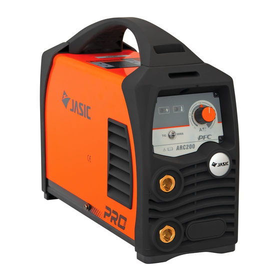
Arc 200 PFC
Manual
Jasic ARC200PFC Manual
Igbt inverterwelder
Hide thumbs
Also See for ARC200PFC
:
Operator's manual
(24 pages)
,
Operator's manual
(13 pages)
1
2
Table Of Contents
3
4
5
6
7
8
9
10
11
12
13
14
15
16
17
18
19
20
21
22
23
24
25
26
27
28
29
30
31
32
33
34
35
36
37
38
39
40
41
42
43
44
45
46
page
of
46
Go
/
46
Contents
Table of Contents
Troubleshooting
Bookmarks
Table of Contents
Table of Contents
Safety Precautions
General Safety
Other Precautions
Description of Symbols
Product Overview
Technical Parameters
Installation
External Interface Description
Power Installation
MMA Electrode Holder and Earth Cable Connection
LIFT TIG Welding Torch and Earth Cable Connection
Wired Hand-Held Remote-Control Connection (Optional)
(Not Optional for Standard Version Without Remote Control Interface)
Installation of Wireless Receiver Module (Optional)
Control Panel
Overview
Display of Parameters and Error Codes
Parameter Adjustment Knob
Selection of Working Mode
Selection of Welding Electrode Diameter for MMA
Selection of MMA Parameters
LIFT TIG Mode Parameter Setting
Protection Indicators
VRD (Voltage Reduction Device) Function Indications
Barcode Display
Restore Factory Settings
Wired Hand-Held Remote Control (Optional)
Wireless Remote Control (Optional)
Welding Function Operation
MMA Operation
LIFT TIG Operation
Maintenance
Power Supply Maintenance
Welding Torch Maintenance
Troubleshooting
Common Malfunction Analysis and Solution
Alarm and Solutions
Packaging, Transportation, Storage and Waste Disposal
Transportation Requirements
Storage Conditions
WEEE Waste Disposal
Appendix 1: Wiring Diagram
Appendix 2: Exploded View of ARC160 and ARC200
Advertisement
Quick Links
1
Table of Contents
2
Description of Symbols
3
Technical Parameters
4
Control Panel
5
Appendix 1: Wiring Diagram
Download this manual
ARC200PFC/ARC160PFC
ARC200/ARC160
IGBT INVERTER WELDER
Copyright©2022 Shenzhen JASIC Technology Co., Ltd.
Table of
Contents
Previous
Page
Next
Page
1
2
3
4
5
Advertisement
Table of Contents
Need help?
Do you have a question about the ARC200PFC and is the answer not in the manual?
Ask a question
Questions and answers
Related Manuals for Jasic ARC200PFC
Welding System Jasic Arc Series Operator's Manual
(24 pages)
Welding System Jasic ARC PFC Series Operator's Manual
Pfc wide voltage (13 pages)
Welding System Jasic ARC140 Operator's Manual
Inverter welder (24 pages)
Welding System Jasic Arc 140 Operating Instructions Manual
Arc series (18 pages)
Welding System Jasic Power Arc 160 PFC Operator's Manual
Power arc series (17 pages)
Welding System Jasic Arc JA-140 Operator's Manual
Dc mma / lift tig (20 pages)
Welding System JASIC ARC400 Operator's Manual
Jasic arc400; arc500 dc mma / lift tig welding machines (17 pages)
Welding System JASIC ARC500 Operator's Manual
Jasic arc400; arc500 dc mma / lift tig welding machines (17 pages)
Welding System JASIC ARC630 Operator's Manual
Jasic arc400; arc500 dc mma / lift tig welding machines (17 pages)
Welding System Jasic Power Arc 180 Operator's Manual
Power arc series (17 pages)
Welding System Jasic ARC200D Operator's Manual
Inverter welder (24 pages)
Welding System Jasic ARC250 Operator's Manual
Inverter welder (24 pages)
Welding System Jasic AC/DC315P Schematic Diagram
(18 pages)
Welding System Jasic ARC160 Manual
Igbt inverterwelder (46 pages)
Welding System Jasic ARC 160GS User Manual
(20 pages)
Welding System Jasic ARC300D Operator's Manual
(24 pages)
This manual is also suitable for:
Arc160pfc
Arc200
Arc160
Table of Contents
Save PDF
Print
Rename the bookmark
Delete bookmark?
Delete from my manuals?
Login
Sign In
OR
Sign in with Facebook
Sign in with Google
Upload manual
Upload from disk
Upload from URL


Need help?
Do you have a question about the ARC200PFC and is the answer not in the manual?
Questions and answers