Table of Contents
Advertisement
Quick Links
Advertisement
Table of Contents

Related Manuals for Owon VDS1022l


Summary of Contents for Owon VDS1022l
- Page 1 VDS Series PC Oscilloscopes User Manual WWW.OWON.COM...
- Page 2 Lilliput Company. Fujian Lilliput Optoelectronics Technology Co.,Ltd.: The Mansion of Optoelectronics, No.19, Heming Road, Lantian Industrial Zone, Zhangzhou, Fujian, China Tel:+86-596-2130430 Fax:+86-596-2109272 Web: www.owon.com Mail: service@owon.com.cn...
- Page 3 Please contact the nearest Lilliput's Sales and Service Offices for services or a complete copy of the warranty statement. For better after-sales service, please visit www.owon.com and register the purchased product online. Excepting the after-sales services provided in this summary or the applicable warranty statements, Lilliput will not offer any guarantee for maintenance definitely declared or hinted, including but not limited to the implied guarantee for marketability and special-purpose acceptability.
-
Page 4: Table Of Contents
Table of Contents VDS Oscilloscope Software Help ................................. ii Ports Introduction ..................................ii VDS1022(I)/ VDS2052(I) ........................................ii VDS2062(L)/VDS3102(L) ........................................ iii VDS2064(L)/VDS3104(L) ........................................ iii General Safety Requirements ..............................iv Safety Terms and Symbols ..............................iv I. PC Software USB Driver Install Guide..........................1 For Windows Vista\Windows 7\Windows 8 ................................... -
Page 5: Vds Oscilloscope Software Help
VDS Oscilloscope Software Help Welcome to VDS Oscilloscope software. The supplied accessories of the oscilloscope include a Quick Guide. The Quick Guide of the oscilloscope and the following helps are for your reference. Minimum PC Requirements Processor: Pentium(R) 4 2.4 GHz Memory: 1 GB Disk space: 1 GB minimum Recommended PC Requirements... -
Page 6: Vds2062(L)/Vds3102(L)
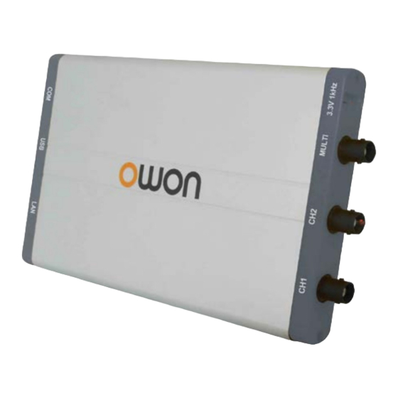
VDS2062(L)/VDS3102(L) Figure: Ports of the Oscilloscope (take VDS3102(L) for instance) 1. USB port: Supply power by PC USB or the adapter; communicate with PC 2. LAN port (optional): Network port which can be used to connect with PC 3. Probe Compensation: Measurement signal (3.3 V/1 kHz) output 4. -
Page 7: General Safety Requirements
General Safety Requirements Before any operations, please read the following safety precautions to avoid any possible bodily injury and prevent this product or any other products connected from damage. In order to avoid any contingent danger, this product is only used within the range specified. Only the qualified technicians can implement the maintenance. -
Page 8: Pc Software Usb Driver Install Guide
I. PC Software USB Driver Install Guide Use the supplied USB cable to connect the oscilloscope with a PC through their USB ports. Note: If you use a USB cable that is not supplied by us, some problems such as connection error and signal disturbing might occur. - Page 9 The next window, select a directory path for the driver software location, and click "Next", Notice: the driver software location is a directory that is under the software setup folder named "USBDRV" (For Windows 8, the location is USBDRV\USBDRV_win8), and the contents inside are like these: Or like this, than you should use the "USBDRV"...
- Page 10 OK, back to the driver installing, after last "Next" step, the system is installing driver software for you, as follow, In the course, It(for Windows XP x86&x64, Windows Vista x86&x64, Windows 7 x86) may open a window named "Windows Security" as below, and just select "Install this driver software anyway"...
- Page 11 Or sometimes it(for Windows 7 x64) may open a window named "Windows Security" as below, and just click "Install" to continue, And then continue installing, And finish. Now a successful installation window opens with information "Windows has successfully updated your driver software".
-
Page 12: For Windows Xp\Windows 200
Close the window, have a look at the "Computer Management" window, you will find a device under [LibUSB-Win32 Devices], it should be like this: Now the USB driver will work. For Windows XP\Windows 2000 Notice: for both x86 and x64. Plug into the running well device to open [Found New Hardware Wizard] dialog. - Page 13 In the Wizard, select [No, not this time] , select [Install from a list or specific location(Advanced)] , select [Search for the best driver in these locations.] , then select [Include this location in the search] and indicate a directory location for USB driver which is named as "USBDRV"...
- Page 14 Then the installation is running, And complete, And prompt as installed, And show installed in [Device Management],...
- Page 15 Now you can use the program and use if for USB communication. If there is an early version of USB driver in your computer, you could try running "reinstall.bat" to fix, the file is under the directory of "USBDRV".
-
Page 16: User Interface
II. User Interface 1. Waveform Display Area 2. Display status, click to choose "Disconnect", "Install USB Driver" or "Connect LAN". Refer to the instruction of the status after this list. 3. The red pointer indicates the horizontal position for the trigger 4. - Page 17 Keyboard Shortcuts F5: Run/Stop Ctrl + Enter: AutoSet Q: The voltage division of Channel 1 decreases one level A: The voltage division of Channel 1 increases one level W: The voltage division of Channel 2 decreases one level S: The voltage division of Channel 2 increases one level ←: Time base decreases one level →: Time base increases one level F1: Open this help document...
-
Page 18: Operations Instruction
III. Operations Instruction Relevant operations of this software. 1.How to Set the Probe Attenuation Coefficient The probe has several attenuation coefficients, which will influence the vertical scale factor of the oscilloscope. To change or check the probe attenuation coefficient in the menu of oscilloscope: (1) Click to show the Function menu, choose "Channel". -
Page 19: How To Set The Horizontal System
Drag the slider up to increase, down to decrease; the further from the center, the higher the changing speed is. Keyboard Shortcuts Q: The voltage division of Channel 1 decreases one level A: The voltage division of Channel 1 increases one level W: The voltage division of Channel 2 decreases one level S: The voltage division of Channel 2 increases one level Cymometer... - Page 20 Trigger Control The oscilloscope provides two trigger types: single trigger and alternate trigger. Single trigger: Use a trigger level to capture stable waveforms in two channels simultaneously. Alternate trigger: Trigger on non-synchronized signals. The Single Trigger and Alternate Trigger menus are described respectively as follows: Single trigger 1.
-
Page 21: How To Set The Channels
Video Trigger Choose Mode as "Video" to trigger on fields or lines of NTSC, PAL or SECAM standard video signals. (1) Select video modulation: NTSC, PAL or SECAM. (2) Set trigger synchronization: Line, Field, Odd filed, Even filed or Line Number. When "Line Number" is selected, you can set the line number. -
Page 22: How To Measure Automatically
(Some models do not have bandwidth limit function) To turn on/off channels Click to choose "CH1" or "CH2", check "On" to turn on the channel, uncheck it to turn off. You can also click the channel switch in Channel window in left bottom. See figure below. To invert a waveform Waveform inverted: the displayed signal is turned 180 degrees against the phase of the earth potential. -
Page 23: How To Implement Sampling Setup
The automatic measurement of voltage parameters The VDS series oscilloscopes provide automatic voltage measurements including Vpp, Vmax, Vmin, Vavg, Vamp, Vrms, Vtop, Vbase, Overshoot and Preshoot. Figure below shows a pulse with some of the voltage measurement points. Vpp: Peak-to-Peak Voltage. Vmax: The maximum amplitude. -
Page 24: How To Measure With Cursors
Sampling Mode Description Sampling Normal sampling mode. Use to capture maximal and minimal samples. Finding highest and lowest Peak Detect points over adjacent intervals. It is used for the detection of the jamming burr and the possibility of reducing the confusion. It is used to reduce the random and don't-care noises, with the editable Average number (1≤... - Page 25 When the Mark Cursor function is disabled, click on the left of the Waveform Display Area to show/hide the Mark Cursor menu. Normal mode 1. Choose source: choose the channel to be measured by cursors between CH1 and CH2. 2. Check measurement type: choose either Time cursor measurement or Voltage cursor measurement,or both. Time cursor measurement: Tick on "Time"...
-
Page 26: How To Set The Display System
Place the mouse cursor on Cursor 1 or Cursor 2, drag after the mouse shape changing to , adjust the position of Cursor 1 and Cursor 2 according to the waveform to be measured. The cursor increment window on the bottom left of FFT window shows current frequency of the two cursors, absolute frequency difference of the two cursors. -
Page 27: Use Mathematical Manipulation Function
Figure: Display in the Vector Form Figure: Display in the Dots Form XY Mode Check "XY Mode", the user interface is switched into Three View mode. Choose the first channel and the second channel. In XY mode widow, the first channel is displayed in the horizontal axis and the second in the vertical axis. Note: XY Mode only support 1k storage memory. - Page 28 2. Click to show Function menu, choose "Math". Check "Math". 3. Choose the factors and operator. Select the voltage division of M. The software transforms the waveform data of the two factors into selected voltage division of M and calculates. The green calculated waveform M is displayed in the screen. Using FFT function The FFT (fast Fourier transform) math function mathematically converts a time-domain waveform into its frequency components.
- Page 29 Good for magnitude, but poorer frequency resolution than Hamming. Recommend to use for: Hanning Sine, periodic and narrow band random noise. Transients or bursts where the signal levels before and after the event are significantly different. The figures below are examples for measuring sine wave with a frequency of 1 kHz under the selection of four different windows for FFT: Figure: Hamming window Figure: Rectangle window Figure: Blackman window...
-
Page 30: How To Zoom The Waveform
DC component or offset can cause incorrect magnitude values of FFT waveform. To minimize the DC component, choose AC Coupling on the source signal. To reduce random noise and aliased components in repetitive or single-shot events, set the oscilloscope acquisition mode to average. What is Nyquist frequency? The Nyquist frequency is the highest frequency that any real-time digitizing oscilloscope can acquire without aliasing. -
Page 31: How To Do Pass/Fail Test
You can also switch and set in Capture&period window as shown in the below. 12.How to do Pass/Fail test The Pass/Fail function monitors changes of signals and output pass or fail signals by comparing the input signal that is within the pre-defined mask. -
Page 32: How To Record And Play A Waveform
Ring: The bell rings when it meets the rule. Stop Once: Stop once it meets the rule. Message Show: Display the counting message on the left top. 5.Enable switch on: Click "Enable". 6.Begin to test: Click "Run". 7.Stop testing: Click "Stop". Save rule Save: Save current rule. -
Page 33: How To Implement The Utility Setting
6. Click "End Record" to stop recording, or wait until the Counter reaches the End Frame. Note: 1.Waveforms of two channels can be recorded simultaneously. 2.You can turn on/off the channels while recording. Only channels turned on can be recorded. If a channel is turned off while recording, there will be no waveform of this channel after the frame when stopped. - Page 34 Language Choose the desired language. Skin Choose Black or Blue for interface skin. Then "Restart" button will appear. After clicking it, the software will be closed and restarted to apply the new skin. Open File Choose BIN waveform file saved and open it, or just drag the file into the software interface to open it. Print Preview Click to open the Print Preview Window.
- Page 35 This function allows to store 8 reference waveforms. These waveforms can be displayed with the current waveform simultaneously. The recalled waveform can't be adjusted. The source can be CH1, CH2 or Math. To save the waveform of CH1 into object "a" and recall it, the steps are as follows: 1.
-
Page 36: How To Use Executive Buttons
MULTI Control the function of the MULTI port in Ports Introduction. Trigger In: Input the trigger signal synchronously Trigger Out: Output the trigger signal synchronously Pass/Fail: Output high level when pass, output low level when fail. 15.How to Use Executive Buttons Executive Buttons include AutoSet , Run/Stop , Single Trigger... - Page 37 (3) Click "Rework" to restart the oscilloscope. 3. Set the network parameters of the software (1) Supply power: Disconnect the USB cable from the computer. Connect it with the AC-DC adapter. Plug the adapter into an electrical outlet to power the oscilloscope. (2) Connection: Plug in the LAN line to the LAN port of the oscilloscope;...
- Page 38 2. Set the network parameters of the oscilloscope (1) Connect via USB and enter the menu: Use the supplied USB cable to connect the oscilloscope with a PC through their USB ports After connecting successfully, click to show Function menu, choose "Utility", click "Network". (2) Set the network parameters of the oscilloscope: In Network menu, click "OK..."...
- Page 39 (4) Click "Connect".
-
Page 40: Technical Specifications
IV. Technical Specifications Unless otherwise specified, the technical specifications applied are for VDS series only, and Probes attenuation set as 10X. Only if the oscilloscope fulfills the following two conditions at first, these specification standards can be reached. This instrument should run for at least 30 minutes continuously under the specified operating temperature. ... - Page 41 Performance Characteristics Instruction VDS3102(L VDS2064(L VDS3104(L Channel –channel 50 Hz: 100 : 1 isolation 10 MHz: 40 : 1 Time delay between 150 ps channel(typical) Dual CH 0.5S/s - 100MS/s VDS1022(I) Single CH 0.5S/s - 100MS/s Dual CH 0.5S/s - 250MS/s VDS2052(I) Single CH 0.5S/s - 250MS/s Dual CH...
- Page 42 Performance Characteristics Instruction Single: Interval(△T) ±(1 interval time+100ppm×reading+0.6ns); accuracy Average>16: (DC - 100MHz) ±(1 interval time +100ppm×reading+0.4ns)
- Page 43 Performance Characteristics Instruction VDS1022(I) VDS2052(I) VDS2062(L 8 bits resolution (2 Channels simultaneously) VDS3102(L A/D converter VDS2064(L 8 bits resolution (4 Channels VDS3104(L simultaneously) VDS1022(I) VDS2052(I) VDS2062(L 5 mV/div – 5 V/div VDS2064(L Sensitivity VDS3102(L 2 mV/div – 5 V/div VDS3104(L VDS1022(I) ±10 div VDS2052(I) ±10 div Vertical...
- Page 44 Performance Characteristics Instruction Average ≥16: ±(3% rdg + 0.05 div) for △V DC accuracy (average) Waveform inverted ON/OFF △V and △T between cursors Cursor Vpp, Vmax, Vmin, Vtop, Vbase, Vamp, Vavg, Vrms, Overshoot, Preshoot, Freq, Period, Rise Time, Fall Time, Delay Automatic A→B , Delay A→B...
- Page 45 Performance Characteristics Instruction Line number range 1-525 (NTSC) and 1-625 (PAL/SECAM) Positive pulse:>, <, = Trigger condition negative pulse:>, <, = Time setting VDS1022(I) VDS2052(I) Slope Trigger VDS2062(L) 30 ns – 10 s VDS3102(L) VDS2064(L) VDS3104(L) Trigger on CH1 Edge, Pulse, *Video, Slope Alternate Trigger Trigger on CH2 Edge, Pulse, *Video, Slope...
- Page 46 Output of the Probe Compensator Performance Instruction Characteristics Output Voltage VDS1022(I) About 5 V, with the Peak-to-Peak voltage ≥ 1 MΩ. (Typical ) VDS2052(I) VDS2062(L) VDS3102(L) About 3.3 V, with the Peak-to-Peak voltage ≥ 1 MΩ. VDS2064(L) VDS3104(L) Frequency (Typical ) Square wave of 1 kHz Power VDS1022(I) 5.0 V / 500 mA...
Need help?
Do you have a question about the VDS1022l and is the answer not in the manual?
Questions and answers