
Related Manuals for Owon VDS6104P


Summary of Contents for Owon VDS6104P
- Page 1 , a product of Lilliput 4-CH VDS6000 Series PC Oscilloscopes (VDS6074/A, VDS6104/A, VDS6104P) User Manual www.owon.com...
- Page 2 OWON products are covered by CHINA and foreign patents, issued and pending. Information in this user manual supersedes that in all previously published material. Specifications change privileges reserved.
- Page 3 Warranty Thanks for choosing OWON product, in the coming days, really hope you will enjoy the time that OWON product accompanies you. OWON product, created and made by Lilliput. Since the delivery date, OWON product been granted 36 natural months’ warranty for device, and 12 months’...
-
Page 4: Table Of Contents
Table of Contents I. General Safety Requirements ....................5 II. Safety Terms and Signs ......................6 III. PC Configuration Requirements ................... 9 IV. Communication Interface Introduction ..................10 V. How to Communicate the Device with PC ................11 i. software installation solution ....................11 ii. -
Page 5: General Safety Requirements
I. General Safety Requirements Safety Warnings ! Before using the device, Lilliput strongly recommend to browse “ ” carefully and completely, so as to avoid any possible human body injury, or any damages to the device, or its accessories, or communicating facility. ! Safety Warnings i. -
Page 6: Safety Terms And Signs
Safety Terms and Signs Safety Terms Terms in this user manual. It covers, Warning which indicates the condition or the operation may cause body injury or permanent life loss. Caution which indicates the condition or the operation may cause device damage, or its accessory damage, or communicated facility damage. - Page 7 To avoid possible human body injury, and / or device damage, and / or its accessory or communicating facility damage, before working the device, Lilliput strongly recommend to read the following safety information, Warning To avoid any potential short circuit or electric shock, DO use the power adapter of original local standard, or recommended by Lilliput.
- Page 8 Warning When the device input is getting through the voltage larger than 42 Vp-p (30Vrms), or on circuit of 4800+VA, to avoid any potential short circuit or electric shock - i. DO use probes and adapter come along with the original device, or those ones recommended by Lilliput. ii.
-
Page 9: Pc Configuration Requirements
III. PC Configuration Requirements Minimum System Requirement - CPU: Pentium® 4/ 2.4 GHz Internal Memory: Effective Hard Disk Space: Recommended System Requirement - CPU: Pentium® Dual-Core/ 2.4 GHz Internal Memory: Effective Hard Disk Space: Other Requirement - Operating System: Windows 11, or Windows 10 / 8 / 7 / Vista / XP (32-bit, or 64-bit) macOS 10.15.x / 10.14.x /... -
Page 10: Communication Interface Introduction
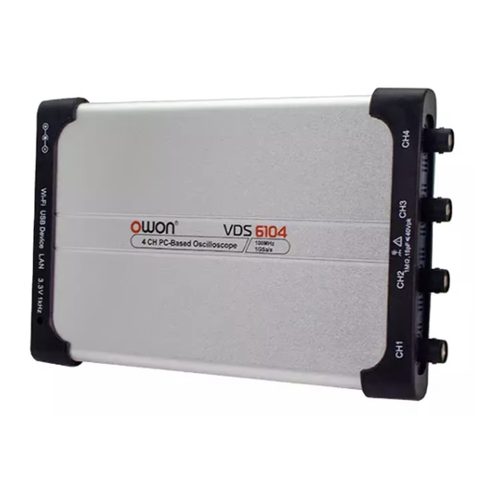
IV. Communication Interface Introduction Figue IV-1. Communication Interface of the Device 1. CH1: for signal input 2. CH2: for signal input 3. CH3: for signal input 4. CH4: for signal input 5. power input: for AC-DC adapter 6. USB host: for Wi-Fi extension 7. -
Page 11: How To Communicate The Device With Pc
V. How to Communicate the Device with PC to communicate the device with PC, it’s a must to install software firstly. i. software installation solution i). full installation Target user(s): general PC oscilloscope user(s), and programmer(s) gets secondary development need Installation process - ... - Page 12 click “Yes” to continue, and following window comes, dot-tick "I accept the above license agreement", then "Next", 12...
- Page 13 another “Next”, to enter into NI Package Manager processing window, then this window, later, when following window appears, 13...
- Page 14 to select additional items you may wish to install, via scroll bar, to select more necessary options, 14...
- Page 15 from here, dot-tick "I accept the above 2 license agreements", again "Next", until this window, dot-tick "I accept the above 2 license agreements" for another time, and another "Next", 15...
- Page 16 to welcome “Review” window, via “Next”, to get access to NI-VISA installation, one more “Next”, 16...
- Page 17 to make your decision at this window, then press “Ok” to finish the whole process, this window indicates the successful installation, to reboot the PC through mouse-clicking “Reboot Now” After PC restarts, the NI-VISA driver been installed onto target PC successfully. 17...
-
Page 18: To Install Pc Software
iii. to install PC Software To run “VDS6000Series_PC_Software.exe” from accompanying CD which comes along with device directly, to install PC software accordingly. iv. to work PC Software Via short-cut to PC software from the desktop of target PC, double-click “VDS6000 Series PC DSO” to start the software. -
Page 19: Operation Interface Of Pc Software
VI. Operation Interface of PC Software 1. Status Indicating Area: please refer to “Status Details List” 2. Main Display Area 3. Red Pointer: to indicate the horizontal position of one conditioned trigger 4. Violet Pointer: to indicate the trigger position in the recorded data 5. - Page 20 Via dragging Red / Yellow / Blue / Purple Pointer upwards or downwards, to adjust the trigger level position of Channel 1 / 2 / 3 / 4. Function Menu: to hide/show it via mouse-clicking ; each side-bar icon matches corresponding function, please refer to Home of Function Menu for details - Shortcut to back to default factory settings, please refer to "Default"...
- Page 21 Status Details List i. following status appears when communicating the device with PC Linking the device is communicating with PC Connect the device successfully communicates with PC Match the PC software is matching the device as per model type Syncing the PC software is synchronizing the device’s settings ii.
-
Page 22: Device Operation
VII. Device Operation i. how to set the probe compensation Before working the probe with any of input channels (Channel 1 / 2 / 3 / 4), better to adjust its compensation, so as to assure ideal measurement effect. Following operation steps to adjust probe compensation - i) From PC software operation interface, mouse-click to get access to device function menu,... - Page 23 choose the ideal option. Or through rotating the mouse wheel, to choose the ideal option. Through zero point position control bar, to reset zero point position will change the vertical position of the signal, via moving the slider upwards, or downwards - the farther slider from the center of control bar, the faster the vertical position changes.
-
Page 24: How To Set The Horizontal System From Pc Software
Frequency Counter The device gets built-in 6-digit frequency counter, with frequency measurement range starts from 2Hz till full bandwidth. iii. how to set the horizontal system from PC software Via “Sample and Period extension window” (as item 16 described under VII. - Page 25 Note: For first operation, after mouse-clicking , the Home of Function Menu comes, to choose "Trigger" option (or mouse-click from right-bottom extension window to show this option). The Trigger option here indicate single trigger, it is the one to use one trigger signal to capture data from two channels, simultaneously, the operation steps - i).
- Page 26 Video Trigger: field / line trigger on standard video signal Slope Trigger: triggers on signal’s rising / falling rate Pulse Trigger: to capture certain pulse width at given trigger condition 1) Edge Trigger i). choose "Edge" from “Mode”, to trigger on the threshold value of input signal; ii).
-
Page 27: How To Set Channel From Pc Software
iii) pick up one trigger synchronization method from Line / Field / Odd Field / Even Field / Line Number. The concrete line number could be set when "Line Number" is picked up. iv) Hold Off setting, please refer to point v) under 1) Edge Trigger. 3) Slope Trigger i) choose "Slope"... - Page 28 to turn on/ turn off Channel 1 / 2 / 3 / 4 Press "CH1", or "CH2", or “CH3”, or “CH4” to choose target channel, check "On" to turn on the target channel, uncheck “On” to turn off the target channel. As alternative method goes, from “Channel extension window for Channel 1 / 2 / 3 / 4”, click right-upper icon as marked below.
-
Page 29: How To Use Automatic Measurement
measure the voltage drop across certain resistor. Press "CH1", or "CH2", or “CH3”, or “CH4” to choose target channel, then check "Measure Current On", to set the A/V ratio (Amps/Volts ratio). Amps/Volts ratio = 1/Resistor value. vi. how to use automatic measurement From Function menu, via , enter into "Measure"... - Page 30 automatic measurement options towards voltage value 10 options involved: Vpp, Vmax, Vmin, Vavg, Vamp, Vrms, Vtop, Vbase, Overshoot and Preshoot. Following illustration to assist better understanding different measurement options, Definitions about these options - voltage between upper peak and lower peak from measured signal Vmax voltage between upper peak and ground (GND) Vmin...
-
Page 31: How To Set Sampling Mode
Vbase voltage between flat base and ground (GND) Overshoot equals (Vmax - Vtop) / Vamp Preshoot equals (Vmin - Vbase) / Vamp the arithmetic average voltage value of complete measured signal, Vavg or chosen part of measured signal true RMS voltage value over complete measured signal, or chosen Vrms part of measured signal automatic measurement options towards time measurement... - Page 32 To know more about different sampling mode - Sampling indicates normal sampling mode Peak Detect this sampling mode always been used to capture interrupting signal noise this sampling mode is to reduce random / irrelevant signal noise, with set range from 1 to Average 128 (1≤...
- Page 33 Following illustration is signal output under Average mode, with average number set in 16, from here, the interrupting signal noise been reduced to certain degree, vertical resolution option this option is available only in VDS6074A / VDS6104A / VDS6104P Via “Precision Mode”, to know more about this option -...
-
Page 34: How To Use Cursor Measurement
8 Bits indicates the device works in 8-bit vertical resolution from ADC 12 Bits indicates the device works in 12-bit vertical resolution from ADC 14 Bits Indicates the device works in 14-bit vertical resolution from ADC viii. how to use cursor measurement From Function menu, via , enter into "Mark Cursor"... - Page 35 voltage cursor measurement: Check "Voltage" option, from the horizontal direction of main display area, two lines in light color appears, indicating Cursor 1 and Cursor 2. When moving mouse pointer through Cursor 1 or Cursor 2, it shapes , drag upwards, or downwards to adjust the measurement range between Cursor 1 and Cursor 2.
-
Page 36: How To Set The Display System
ix. how to set the display system From Function menu, via , enter into "Display" option. Available in 2 display type, “Vector” and “Dots”. Vector to fill the room between the two adjacent sampling points, in dots of vector Dots to display sampling points only The signal displayed in Vector, In contrast with the same signal displayed in Dots,... -
Page 37: How To Change Utility Setting
XY Mode Check "XY Mode", the main display area switches to 3-window VIEW mode. In the XY mode window ( upper-left window), the first channel reflects in X axis, the second channel in Y axis. Note: When the device works in XY Mode, the record length been restricted at 1K points. The record length setting changes to 1K points automatically. - Page 38 Language Available in 2 options: English and Chinese (simplified). Skin Works for operation interface skin color, either Black or Blue. After different color chosen from the current one, “Restart Effect” option comes, press "Restart" after the option, the PC software will restart in newly-set operation interface skin color.
-
Page 39: How To Use Main Action Button
Based upon the current record length, to export the captured signal in certain format file, with format supports .zip, .csv. Mouse-click from right-bottom functions the same as pressing “Pause & Export” button. Self Cal Via “Self Cal” operation, the device may reach the best ideal working status within short time, which assures the most accurate measurement result accordingly. -
Page 40: How To Use Socket Connection
Trigger Trigger Type Edge, or Video, as per the input signal Trigger Mode Auto Trigger Coupling Trigger Slope Rise Trigger Level mid-point setting Channel Turn On / Off Channels turn on the channel with signal input Zero Point Position been adjusted to the proper position Vertical Scale been adjusted to the proper division Horizontal Level... - Page 41 ii) to communicate device with PC a. to power the device through adapter, or through USB connection cable via suitable USB communication interface; b. to communicate the device with PC via crossed network cable, each end connects each LAN port; c.
- Page 42 when the device communicates with PC by router connection For device, its default IP address / port goes in 192.168.1.172 / 8866. When device communicates with PC by direct LAN cable, the first 3 segments from the default IP address of PC should read the same as those from the device, giving an example, both of 2 parties reads 192.168.1.xxx (the last segment “xxx”...
- Page 43 ii) to communicate device with PC a. to power the device through adapter, or through USB connection cable via suitable USB communication interface; b. to communicate the device with PC via same router, with respective network cable connects from LAN port to same router; c.
-
Page 44: How To Use Lan Communication Interface
xiii. how to use LAN communication interface Through LAN communication interface, the device may communicate with PC directly, or via router connection the device communicates with PC by direct LAN i) to check target PC’s network setting giving an example, here we set IP address in 192.168.1.71 ii) to set device’s network via “Network”... - Page 45 c. press “OK” to finish the “MachineNetSetting” to add NI network device iii) a. device powering. Either through AC adapter, or through USB connection cable, the device been powered, with indicator lights red for seconds. b. LAN connection. To communicate device with target PC through LAN connection, via respective LAN communication interface.
- Page 46 via “Devices and Interfaces”, then “Network Devices”, enter into “Add Network Device” press dot-tick “Auto-detect of LAN Instrument”, then “Next” 46...
- Page 47 to following window, to choose “TCPIP0::(the previous IP connection dot-tick “Select instrument(s) detected on local subnet”, just added)::inst0::INSTR”, then mouse-click “Finish”. back to PC software, to press TCPIP0::(the previous IP connection just added)::inst0::INSTR to communicate with PC software, 47...
- Page 48 the device communicates with PC by router connection i) to check target PC’s network setting, the Netmask and Gateway setting should read the same as the one for router, giving an example, provided the router / PC’s network setting goes in - IP Address: 192.168.1.71 Netmask:...
- Page 49 c. press “OK” to finish the “MachineNetSetting” iii) to add NI network device a. device powering. Either through AC adapter, or through USB connection cable, the device been powered, with indicator lights red for seconds. b. LAN connection. To communicate device with target PC through LAN connection, via respective LAN communication interface.
- Page 50 via “Devices and Interfaces”, then “Network Devices”, enter into “Add Network Device” press dot-tick “Auto-detect of LAN Instrument”, then “Next” 50...
- Page 51 to following window, to choose “TCPIP0::(the previous IP connection dot-tick “Select instrument(s) detected on local subnet”, just added)::inst0::INSTR”, then mouse-click “Finish”. back to PC software, to press TCPIP0::(the previous IP connection just added)::inst0::INSTR to communicate with PC software, 51...
-
Page 52: How To Work Wifi With Pc Software
xiv. how to work WiFi with PC software Note: Only the device equipped with optional WiFi module gets this function. to work WiFi with PC software through device hotspot The target PC should support WiFi communication, and the optional WiFi module should be inserted into USB host communication interface. - Page 53 via “Devices and Interfaces”, then “Network Devices”, enter into “Add Network Device” e. press dot-tick “Auto-detect of LAN Instrument”, then “Next” f. to following window, 53...
- Page 54 to choose “TCPIP0::(the previous IP connection dot-tick “Select instrument(s) detected on local subnet”, just added)::inst0::INSTR”, then mouse-click “Finish”. g. back to PC software, to press TCPIP0::(the previous IP connection just added)::inst0::INSTR to communicate with PC software, 54...
- Page 55 “SSID” and “Password” from WiFi router, here we use one available WiFi router - SSID in OWON, Password in lilliputowon, press “OK” to confirm the setting, after the step, “WiFiSetting” menu will be off. Re-enter “WiFiSetting” menu, press “Refresh” to update the IP address.
- Page 56 ii) to add NI network device a. device powering. To disconnect the USB communication between the device and target PC, with AC adapter get through power source, then power the device, with indicator lights red for seconds. b. WiFi communication. To communicate the device with target PC through WiFi hotspot set onto device, as per correct SSID and Password.
- Page 57 e. press dot-tick “Auto-detect of LAN Instrument”, then “Next” f. to following window, to choose “TCPIP0::(the previous IP connection dot-tick “Select instrument(s) detected on local subnet”, 57...
- Page 58 just added)::inst0::INSTR”, then mouse-click “Finish”. g. back to PC software, to press TCPIP0::(the previous IP connection just added)::inst0::INSTR to communicate with PC software, 58...
-
Page 59: Technical Specifications
70 MHz 14-bit mode 20 MHz Bandwidth VDS6104 100MHz 8-bit mode 100 MHz VDS6104A 12-bit mode 100 MHz VDS6104P 14-bit mode 20 MHz VDS6074 8 bits VDS6104 Vertical Resolution (A/D) VDS6074A VDS6104A 8 bits / 12 bits / 14 bits VDS6104P... - Page 60 0.5 Sa/s - 500 MSa/s VDS6074A 2-CH VDS6104A 12-bit mode 0.5 Sa/s - 250 MSa/s working VDS6104P 14-bit mode 0.5 Sa/s - 125 MSa/s 8-bit mode 0.5 Sa/s - 1 GSa/s 1-CH 12-bit mode 0.5 Sa/s - 500 MSa/s working 14-bit mode 0.5 Sa/s - 125 MSa/s...
- Page 61 ± 20 V (100 mV/div - 500 mV/div) ± 40 V (1 V/div - 5 V/div) VDS6074 70 MHz VDS6074A Analog Bandwidth VDS6104 VDS6104A 100 MHz VDS6104P Low Frequency Vertical ≥10 Hz (at BNC) (AC coupling, -3dB) System VDS6074 ≤ 5.0 ns VDS6074A...
- Page 62 Trigger Internal Trigger Level Range ±5 divisions from the screen center Trigger Level Internal Accuracy (typical) ±0.3 division (working for signal with rise time / fall time ≥ 20ns ) Trigger changing according to different record length and time base Displacement Trigger Hold-off 100ns - 10s...
- Page 63 Mechanical Device Dimension w/h/d 190 x 120 x 18 mm Weight 0.38 kg Device Calibration Time Interval After the device been operated for every 12 natural months (calculated from the first operation day), better to calibrate it one time. 63...
-
Page 64: Appendix
IX. Appendix Appendix A. Device Accessory List Accessories - 4 x passive probe 1 x USB connection cable (type-C) 1 x hard copy quick guide 1 x AC-DC adapter 1 x PC software / user manual CD ... -
Page 65: Appendix B. Device Maintenance
After device surface cleaning, before working the device for next time, please confirm that the device surface in a relative dry condition, so as to avoid any possible short circuit risk, or possible human body injury caused by electric Conduction from the wet surface. Lilliput (OWON) 12/2020 ISSUE, in V1.0.3 65...
Need help?
Do you have a question about the VDS6104P and is the answer not in the manual?
Questions and answers