Table of Contents
Advertisement
Quick Links
Advertisement
Table of Contents

Related Manuals for MPP Solar LVX 6048


Summary of Contents for MPP Solar LVX 6048
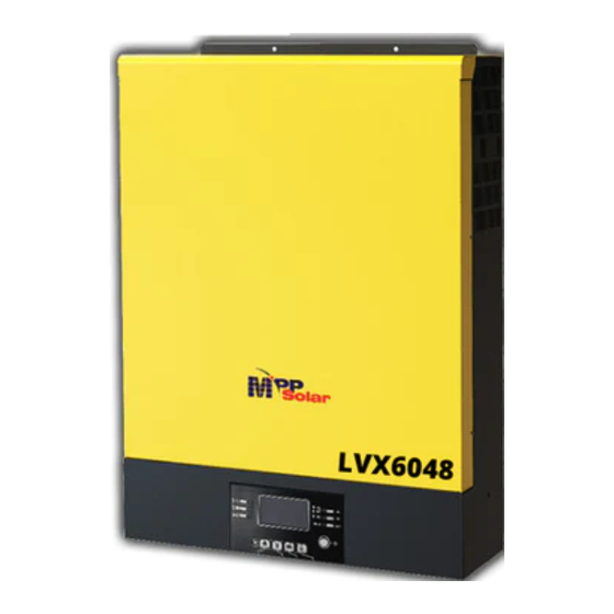
- Page 1 User Manual LVX 6048 INVERTER / CHARGER Version: 1.6...
-
Page 2: Table Of Contents
Table Of Contents ABOUT THIS MANUAL ............................. 1 Purpose ................................1 Scope ................................1 SAFETY INSTRUCTIONS ..........................1 INTRODUCTION ............................... 2 Product Overview ............................. 3 INSTALLATION ..............................4 Unpacking and Inspection..........................4 Preparation ..............................4 Mounting the Unit ............................. 4 Battery Connection ............................ -
Page 3: About This Manual
ABOUT THIS MANUAL Purpose This manual describes the assembly, installation, operation and troubleshooting of this unit. Please read this manual carefully before installations and operations. Keep this manual for future reference. Scope This manual provides safety and installation guidelines as well as information on tools and wiring. SAFETY INSTRUCTIONS WARNING: This chapter contains important safety and operating instructions. -
Page 4: Introduction
INTRODUCTION This hybrid PV inverter can provide power to connected loads by utilizing PV power, utility power and battery power. Hybrid inverter Distribution Box PV module Electric grids Load Battery Figure 1 Basic hybrid PV System Overview Depending on different power situations, this hybrid inverter is designed to generate continuous power from PV solar modules (solar panels), battery, and the utility. -
Page 5: Product Overview
Product Overview NOTE: For parallel model installation and operation, please check separate parallel installation guide for the details. LCD display Status indicator Charging indicator Fault indicator Function buttons Power on/off switch AC input connectors AC output connectors (Load connection) PV connectors 10. -
Page 6: Installation
INSTALLATION Unpacking and Inspection Before installation, please inspect the unit. Be sure that nothing inside the package is damaged. You should have received the following items inside of package: Inverter unit Software CD Manual RS-232 cable Preparation Before connecting all wirings, please take off bottom cover by removing four screws as shown below. Mounting the Unit Consider the following points before selecting where to install: Do not mount the inverter on flammable construction materials. -
Page 7: Battery Connection
Torque Amperage Capacity Value Cable Dimensions D (mm) L (mm) LVX 6048 137A 200AH 1*2AWG 33.2 2~3 Nm Please follow below steps to implement battery connection: 1. Assemble battery ring terminal based on recommended battery cable and terminal size. 2. Insert the ring terminal of battery cable flatly into battery connector of inverter and make sure the nuts are tightened with torque of 2-3 Nm. -
Page 8: Ac Input/Output Connection
Suggested cable requirement for AC wires Model Gauge Torque Value LVX 6048 10 AWG 1.2~ 1.6 Nm Please follow below steps to implement AC input/output connection: 1. Before making AC input/output connection, be sure to open DC protector or disconnector first. -
Page 9: Pv Connection
To reduce risk of injury, please use the proper recommended cable size as below. Model Typical Amperage Cable Size Torque LVX 6048 10AWG 2.0~2.4Nm PV Module Selection: When selecting proper PV modules, please be sure to consider below parameters: 1. -
Page 10: Final Assembly
Recommended PV module Configuration PV Module Spec. Total solar input power Solar input Q'ty of modules (reference) 1500W 6 pieces in series 6 pcs - 250Wp 2000W 8 pieces in series 8 pcs - Vmp: 30.7Vdc 2750W 11 pieces in series 11 pcs - Imp: 8.15A - Voc: 37.4Vdc... -
Page 11: Dry Contact Signal
Please use supplied communication cable to connect to inverter and PC. Insert bundled CD into a computer and follow on-screen instruction to install the monitoring software. For the detailed software operation, please check user manual of software inside of CD. Wi-Fi Connection Wi-Fi module can enable wireless communication between off-grid inverters and monitoring platform. -
Page 12: Operation
OPERATION Power ON/OFF Once the unit has been properly installed and the batteries are connected well, simply press On/Off switch (located on the button of the case) to turn on the unit. Operation and Display Panel The operation and display panel, shown in below chart, is on the front panel of the inverter. It includes three indicators, four function keys and a LCD display, indicating the operating status and input/output power information. -
Page 13: Lcd Display Icons
Function Keys Function Key Description Exit the setting Reserved Reserved Reserved Reserved To last selection Down To next selection Enter To confirm/enter the selection in setting mode LCD Display Icons Icon Function Input source information Indicates the AC input Indicates the PV1 panel input Left digital display information Indicate input voltage, input frequency, battery voltage, PV voltage, charger current... -
Page 14: Lcd Setting
Indicates battery level by 0-24%, 25-49%, 50-74% and 75-100% and charging status. Load information Indicates overload. Indicates the load level by 0-24%, 25-49%, 50-74%, and 75-100%. 0%~24% 25%~49% 50%~74% 75%~100% Mode operation information Indicates unit connects to the mains. Indicates unit connects to the 1 PV panel Indicates the solar charger is working Indicates the DC/AC inverter circuit is working. - Page 15 only when battery voltage drops to either low-level warning voltage or the setting point in program 20 or solar and battery is not sufficient. Appliances (default) If selected, acceptable AC input voltage range will be within 65-140VAC. AC input voltage range If selected, acceptable AC input voltage range will be within 95-140VAC.
- Page 16 Feed to grid enable Solar energy feed to grid enable. If this inverter/charger is working in Line, Standby or Fault mode, charger source can be programmed as below: Solar first Solar energy will charge battery as first priority. Utility will charge battery only when solar energy is not available.
- Page 17 Soltaro battery If selected, programs of 11, 17, 18 and 19 will be automatically set up. No need for further setting. LIb-protocol Select “ LIb” if using Lithium battery compatible to Lib protocol. If selected, programs of 11, 17, 18 and Battery type 19 will be automatically set up.
- Page 18 Battery fully charged The setting range is from 48V to 58V and increment of each click is 1V. Default setting: 54V Battery stop charging voltage when grid is available 10% (default) If “WECO battery” is selected in program 14, this parameter will refer to the SOC of battery and adjustable from 10% to 100%.
- Page 19 00:00 (Default) Start charging time for AC charger The setting range of start charging time for AC charger is from 00:00 to 23:00, increment of each click is 1 hour. 00:00 (Default) Stop charging time for AC charger The setting range of stop charging time for AC charger is from 00:00 to 23:00, increment of each click is 1 hour.
-
Page 20: Display Setting
Display Setting The LCD display information will be switched in turns by pressing “UP” or “DOWN” key. The selectable information is switched as below order: input voltage, input frequency, PV voltage, charging current, battery voltage, output voltage, output frequency, load percentage, load in Watt, load in VA, load in Watt, DC discharging current, main board firmware version and SCC firmware version. - Page 21 Input2 frequency and output2 frequency Input2 frequency=60.0Hz, output2 frequency=60.0Hz Battery voltage and output1 voltage Battery Voltage=48.0V, output1 voltage=120V Battery voltage and output2 voltage Battery Voltage=48.0V, output2 voltage=120V Battery voltage and load1 percentage Battery Voltage=48.0V, load1 percentage = 68%...
- Page 22 Battery voltage and load2 percentage Battery Voltage=48.0V, load2 percentage = 68% Battery voltage and load1 in VA Battery Voltage=48.0V, load1 in VA=1.08kVA Battery voltage and load2 in VA Battery Voltage=48.0V, load2 in VA=1.08kVA Battery voltage and load1 in Watt Battery Voltage=48.0V, load1 in Watt=1.88kW...
- Page 23 Battery voltage and load2 in Watt Battery Voltage=48.0V, load2 in Watt=1.88kW PV1 voltage and PV power PV1 Voltage=360V, PV power=1.58kW Charger current and Charging current=30A, discharging current=0A DC discharging current PV energy generated today Today energy = 6.3kWh PV energy generated this month This month energy = 358kWh...
- Page 24 PV energy generated this year This year energy = 8.32MWh PV energy generated totally Total energy = 13.9MWh Real date Real date Nov 28, 2016. Real time Real time 13:20. Main CPU version checking. Main CPU version 00001.00...
-
Page 25: Operating Mode Description
Secondary CPU version checking. Secondary CPU version 00020.21 Operating Mode Description Operating mode Behaviors LCD display Battery is charged by utility. Battery is charged by PV energy. Standby mode Note: *Standby mode: The inverter Battery is charged by utility and PV energy. is not turned on yet but at this time, the inverter can charge battery without AC... - Page 26 PV energy and utility charge battery, and utility provides power to load. PV energy charges battery, utility and PV energy provide power to the load. Output power from utility. Charger available PV energy charges battery, PV energy provides power to the load and feeds remaining energy to the grid. PV energy and battery energy supply power to the load.
- Page 27 Warning Indicator Warning Code Warning Event Icon flashing Fan locked Over temperature Battery over charged Low battery Overload Inverter power derating PV is weak Battery is not connected...
- Page 28 Faults Reference Code Fault Code Fault Event Icon on Fan is locked. Over temperature Battery voltage is too high. Battery voltage is too low. Output is short circuited. Output voltage is abnormal. Overload time out. Bus voltage is too high. Bus soft start failure.
-
Page 29: Specifications
SPECIFICATIONS MODEL LVX 6048 RATED OUPUT POWER 6000W PV INPUT (DC) Max. PV Power 6000W Max. Input voltage 450 VDC (Maximum PV open voltage) Max. DC Power MPPT range 222 VDC~430 VDC Working MPP range 120 VDC~430 VDC Max. DC Input current / per string... -
Page 30: Trouble Shooting
TROUBLE SHOOTING Problem LCD/LED/Buzzer Explanation / Possible cause What to do Unit shuts down LCD/LEDs and buzzer automatically will be active for 3 The battery voltage is too low 1. Re-charge battery. during startup seconds and then (<1.91V/Cell) 2. Replace battery. process. -
Page 31: Appendix I: Parallel Function
Appendix I: Parallel function 1. Introduction This inverter can be used in parallel in only split phase equipment. Maximum nine units work together to support split phase equipment. The supported maximum output power is 54KW/54KVA. NOTE: If this unit is bundled with share current cable and parallel cable, this inverter is default supported parallel operation. - Page 32 Step 3: Remove two screws as below chart to take out cover of parallel communication. Step 4: Install new parallel board with 2 screws tightly. Step 6: Connect 2-pin to original position. Step 7: Put communication board back to the unit. Step 8: Put wire cover back to the unit.
- Page 33 Recommended AC input and output cable size for each inverter: Model AWG no. Torque LVX 6048 10 AWG 1.2~1.6Nm You need to connect the cables of each inverter together. Take the battery cables for example: You need to use a connector or bus-bar as a joint to connect the battery cables together, and then connect to the battery terminal.
- Page 34 230VAC 230VAC Note1: Also, you can use 50A for LVX 6048 for only 1 unit and install one breaker at its AC input in each inverter. Note2: Regarding split phase system, you can use 3-pole breaker directly and the rating of the breaker should...
- Page 35 Three inverters in parallel: Power Connection Load Communication Connection ❶ ❷ ❸ Four inverters in parallel: Power Connection Load...
- Page 36 Communication Connection ❶ ❷ ❸ ❹ Five inverters in parallel: Power Connection Load Communication Connection ❶ ❷ ❸ ❹ ❺ Six inverters in parallel: Power Connection Load Communication Connection ❶ ❷ ❸ ❹ ❺ ❻...
- Page 37 Seven inverters in parallel: Power Connection Load Communication Connection ❶ ❷ ❸ ❹ ❺ ❻ ❼ Eight inverters in parallel: Power Connection Load Communication Connection ❶ ❷ ❸ ❹ ❺ ❻ ❼ ❽ Nine inverters in parallel: Power Connection Load Communication Connection ❶...
- Page 38 7. PV Connection Please refer to user manual of single unit for PV Connection. CAUTION: Each inverter should connect to PV modules separately. 7. LCD Setting and Display Setting Program: Program Description Selectable option Single: When selected, the unit is used in single AC output mode operation.
- Page 39 9. Commissioning Step 1: Check the following requirements before commissioning: Correct wire connection Ensure all breakers in Line wires of load side are open and each Neutral wires of each unit are connected together. Step 2: Turn on each unit and set “PAL” in LCD setting program 28 of each unit. And then shut down all units. NOET: It’s necessary to turn off switch when setting LCD program.
- Page 40 type. Otherwise, please contact your installer to provide SOP to calibrate battery voltage of each inverter. If the problem still remains, please contact your installer. Check the utility wiring conncetion and restart the inverter. AC input voltage and Make sure utility starts up at same time. If there are breakers installed frequency are detected between utility and inverters, please be sure all breakers can be turned different.
-
Page 41: Appendix Ii: Bms Communication Installation
Appendix II: BMS Communication Installation 1. Introduction If connecting to lithium battery, it is recommended to purchase a custom-made RJ45 communication cable. Please check with your dealer or integrator for details. This custom-made RJ45 communication cable delivers information and signal between lithium battery and the inverter. - Page 42 PYLONTECH Dip Switch: There are 4 Dip Switches that sets different baud rate and battery group address. If switch position is turned to the “OFF” position, it means “0”. If switch position is turned to the “ON” position, it means “1”. Dip 1 is “ON”...
- Page 43 * For multiple battery connection, please check battery manual for the details. Note for parallel system: 1. Only support common battery installation. 2. Use custom-made RJ45 cable to connect any inverter (no need to connect to a specific inverter) and Lithium battery.
- Page 44 PYLONTECH After configuration, please install LCD panel with inverter and Lithium battery with the following steps. Step 1. Use custom-made RJ45 cable to connect inverter and Lithium battery. Note for parallel system: 3. Only support common battery installation. 4. Use custom-made RJ45 cable to connect any inverter (no need to connect to a specific inverter) and Lithium battery.
- Page 45 WECO Step 1. Use custom-made RJ45 cable to connect inverter and Lithium battery. Note for parallel system: 1. Only support common battery installation. 2. Use custom-made RJ45 cable to connect any inverter (no need to connect to a specific inverter) and Lithium battery.
- Page 46 SOLTARO Step 1. Use custom-made RJ45 cable to connect inverter and Lithium battery. Note for parallel system: 1. Only support common battery installation. 2. Use custom-made RJ45 cable to connect any inverter (no need to connect to a specific inverter) and Lithium battery.
- Page 47 5. LCD Display Information Press “UP” or “DOWN” key to switch LCD display information. It will show battery pack and battery group number before “Main CPU version checking” as below screen. Selectable information LCD display Battery pack numbers & Battery pack numbers = 3, battery group numbers = 1 Battery group numbers 6.
-
Page 48: Appendix Iii: Approximate Back-Up Time Table
1226 2576 1000 1226 1500 2000 2500 3000 LVX 6048 3500 4000 4500 5000 5500 6000 Note: Backup time depends on the quality of the battery, age of battery and type of battery. Specifications of batteries may vary depending on different manufacturers. -
Page 49: Appendix Iv: The Wi-Fi Operation Guide In Remote Panel
Appendix IV: The Wi-Fi Operation Guide in Remote Panel 1. Introduction Wi-Fi module can enable wireless communication between off-grid inverters and monitoring platform. Users have complete and remote monitoring and controlling experience for inverters when combining Wi-Fi module with SolarPower APP, available for both iOS and Android based device. All data loggers and parameters are saved in iCloud. - Page 50 Then, a “Registration success” window will pop up. Tap “Go now” to continue setting local Wi-Fi network connection. Step 2: Local Wi-Fi Module Configuration Now, you are in “Wi-Fi Config” page. There are detailed setup procedure listed in “How to connect?” section and you may follow it to connect Wi-Fi.
- Page 51 Then, return to SolarPower APP and tap “ ” button when Wi-Fi module is connected successfully. Step 3: Wi-Fi Network settings icon to select your local Wi-Fi router name (to access the internet) and enter password. Step 4: Tap “Confirm” to complete the Wi-Fi configuration between the Wi-Fi module and the Internet. If the connection fails, please repeat Step 2 and 3.
- Page 52 Diagnose Function If the module is not monitoring properly, please tap “ ” on the top right corner of the screen for further details. It will show repair suggestion. Please follow it to fix the problem. Then, repeat the steps in the chapter 4.2 to re-set network setting.
- Page 53 Overview After login is successfully, you can access “Overview” page to have overview of your monitoring devices, including overall operation situation and Energy information for Current power and Today power as below diagram. Devices Tap the icon (located on the bottom) to enter Device List page. You can review all devices here by adding or deleting Wi-Fi Module in this page.
- Page 54 Part number label is pasted on the bottom of remote LCD panel. For more information about Device List, please refer to the section 2.4. In ME page, users can modify “My information”, including【User’s Photo】,【Account security】, 【Modify password】,【Clear cache】,and【Log-out】, shown as below diagrams. 2.2.
- Page 55 Device Mode On the top of screen, there is a dynamic power flow chart to show live operation. It contains five icons to present PV power, inverter, load, utility and battery. Based on your inverter model status, there will be 【Standby Mode】,【Line Mode】,【Battery Mode】.
- Page 56 Swipe left 【Basic Information】 displays basic information of the inverter, including AC voltage, AC frequency, PV input voltage, Battery voltage, Battery capacity, Charging current, Output voltage, Output frequency, Output apparent power, Output active power and Load percent. Please slide up to see more basic information. 【Production Information】displays Model type (Inverter type), Main CPU version and secondary CPU version.
- Page 57 Please refer to below parameter setting list for an overall description and be noted that the available parameters may vary depending on different models. Please always see the original product manual for detailed setting instructions. Parameter setting list: Item Description Output setting Output source To configure load power source priority.
- Page 58 Record happens. Solar Supply Set solar power as priority to charge the battery or to power the load. Priority Reset PV If clicked, PV energy storage data will be reset. Energy Storage Start Time For The setting range of start charging time for AC charger is from 00:00 to Enable AC 23:00.
Need help?
Do you have a question about the LVX 6048 and is the answer not in the manual?
Questions and answers