Table of Contents
Advertisement
Quick Links
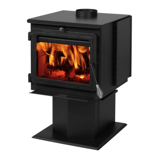
15‐SSW01, 50‐SHSSW01, 50‐TRSSW01
INSTALLATION & OPERATION MANUAL
Manufactured By:
England's Stove Works, Inc.
PO Box 206
Monroe, VA 24574
www.heatredefined.com
(800) 245‐6489
Rev. 1/2021
CAUTION
Please read this entire manual before installation and use of this wood fuel‐
burning appliance. Keep children, furniture, fixtures and all combustibles away
from any heating appliance.
SAVE THESE INSTRUCTIONS
SAFETY NOTICE
Failure to follow these instructions can result in property damage, bodily injury
or even death. For your safety and protection, follow the installation
instructions outlined in this manual. Contact your local building or fire officials
about restrictions and installation inspection requirements (including permits)
in your area.
La version française de ce manuel suit la version anglaise.
Advertisement
Table of Contents

Related Manuals for England's Stove Works Smartstove 15-SSW01


Summary of Contents for England's Stove Works Smartstove 15-SSW01
- Page 1 15‐SSW01, 50‐SHSSW01, 50‐TRSSW01 INSTALLATION & OPERATION MANUAL Manufactured By: England’s Stove Works, Inc. PO Box 206 Monroe, VA 24574 www.heatredefined.com (800) 245‐6489 Rev. 1/2021 CAUTION Please read this entire manual before installation and use of this wood fuel‐ burning appliance. Keep children, furniture, fixtures and all combustibles away from any heating appliance. SAVE THESE INSTRUCTIONS SAFETY NOTICE Failure to follow these instructions can result in property damage, bodily injury or even death. For your safety and protection, follow the installation instructions outlined in this manual. Contact your local building or fire officials about restrictions and installation inspection requirements (including permits) in your area. La version française de ce manuel suit la version anglaise. ...
- Page 2 IMPORTANT: IF YOU HAVE A PROBLEM WITH THIS UNIT, DO NOT RETURN IT TO THE DEALER. CONTACT TECHNICAL SUPPORT @ 1‐800‐245‐6489 Mobile Home Use (Approved for USA only): This freestanding wood unit is approved for mobile home or doublewide installation with the outside combustion air hook‐ up. See the “Installation” section of this manual for details pertaining to mobile home installations. Mobile home installation must be in accordance with the Manufactured Home and Safety Standard (HUD), CFR 3280, Part 24. Retain for your files Model Number Date of Purchase Date of Manufacture Serial Number * This information can be found on the safety tag attached to the rear of the unit. Have this information on hand if you phone the factory or your dealer regarding this product. CAUTION • Keep children away. • Supervise children in the same room as this appliance. • Alert children and adults to the hazards of high temperatures. • Do NOT operate with protective barriers open or removed. • Hot while in operation! Keep clothing, furniture, draperies and other combustibles away. Contact may cause skin burns! • Installation MUST comply with local, regional, state and national codes and regulations.
- Page 3 IMPORTANT NOTE: The ash pan on this wood stove must be installed correctly before operation. The locking lip on the bottom of the ash pan must be slid INSIDE the stove pedestal so that it can lock the ash pan in place, flush against the pedestal. Tilt the ash pan up toward you as you slide it into the opening to do this.
-
Page 4: Table Of Contents
WELCOME! • Inspecting Gaskets ...... 23 Introduction • Thank You! …....... 5 • Finish .......... 23 Specifications Replacing Components • Heating Specifications.... 6 • Glass ........... 24 • Dimensions........ 6 • Burner Tubes ...... 25 • EPA Compliance ...... 6 • Ceramic Fiberboards.... 25 • Door Hinges ........ 25 Installation • Heat Shield & Back Panel ... 25 • Installation Overview .... 7 • Other Components ..... 26 •... -
Page 5: Thank You
Thank you for purchasing this fine product from England’s Stove Works! England's Stove Works was started, and is still owned by, a family that believes strongly in a "Do It Yourself" spirit – that’s one reason you found this product at your favorite “Do It Yourself” store. -
Page 6: Specifications
SPECIFICATIONS Heating Specifications • Maximum Burn Time** ................. 6‐8 hours • Approximate Square Footage Heated*** ............ 2000 sq. ft. • Firebox Capacity.................... 35 pounds • Flue Collar .................... 6 .0 in. round Dimensions (Inches) EPA and Safety Compliance Specifications EPA Compliance Status …….. Certified to comply with 2020 particulate emission standards using crib wood fuel. U.S. Test Standard: US EPA 40 CFR Part 60, Subpart 60.536 Particulate Emissions …………………………… 1.956 grams/hr CO Emissions ………………………………………. 1.659 grams/min Heat Output Range …………………………….. 11,129 – 24,369 Btu/hr Efficiency…… ……………………………………… 73.77% (HHV) UL 1482‐2011(R2015) and ULC‐S627‐ Tested To EPA Test Method 28A, ASTM E2780, ASTM E2515, 00(R2016). Notes for this unit: Product may vary slightly from diagram. Clearances are the minimum for this unit and may need to be increased in the rear to have proper vent clearances. -
Page 7: Installation
INSTALLATION Installation Overview When choosing a location for your new stove, there are a multitude of factors that should be taken into account before beginning the installation. 1. Traffic Patterns – To help prevent accidents, the stove should be placed in a location where it is out of the way of normal travel through the home. 2. Heat Flow – When deciding on a location for the stove, consider the way heat moves throughout your home. Install the stove where you need the heat; basement installations often do not allow sufficient heat to flow to the upper floors and a top floor installation will not allow any heat to reach the floors below. Always consider that heat rises and will take the path of least resistance while it is still hot. 3. Exhaust Location – The engine which drives a wood stove is the chimney system, so it is important to consider precisely how the chimney system will be integrated into the stove installation. Ideally, a wood stove chimney will run completely vertical from the flue collar of the unit all the way to the termination point above the roof line. Keeping the entire chimney system inside the heated envelope of the home will ensure a strong, easy to initiate draft in the chimney. Although exterior chimney systems often function properly, they are more likely to suffer from cold down drafts at start up or provide weak draft to the unit. Also, consider the cross‐sectional area of the chimney; although existing masonry chimneys can often be used, a large external masonry chimney will result in a unit that is difficult or impossible to operate properly. In that case, an insulated chimney liner will often be required to supply the necessary draft. 4. Wall Construction – Locating the stove so that the exhaust system can pass between studs will simplify the installation and eliminate the need to reframe any sections of the wall or ceiling to accommodate the wall thimble or ceiling box. WARNING ... -
Page 8: Clearances To Combustibles
INSTALLATION Clearances to Combustibles Parallel Corner Installation Wall Installation WARNING ‐ INSTALL VENT AT CLEARANCES SPECIFIED BY THE VENT MANUFACTURER Chimney Chimney Chimney Unit to Side Connector Unit to Unit to Connector to Connector Wall * to Side ... -
Page 9: Venting Introduction
INSTALLATION Venting Introduction Venting Guidelines • ALWAYS install vent pipe in strict This wood stove operates on a natural draft system, in which the chimney adherence to the instructions and system pulls air through the stove. This unit clearances included with your must be installed in accordance with the venting system. following detailed descriptions of venting • DO NOT CONNECT THIS WOOD techniques; not installing the stove in STOVE TO A CHIMNEY FLUE WHICH accordance with the details listed here can ALSO SERVES ANOTHER APPLIANCE. result in poor stove performance, property • DO NOT install a flue pipe damper damage, bodily injury or death. Avoid or any other restrictive device in the make‐shift compromises when installing the exhaust venting system of this unit. venting system. England’s Stove Works is • USE an approved wall thimble when not responsible for any damage incurred passing through a wall and a ceiling due to a poor or unsafe installation. support/fire stop when passing Be certain that all aspects of the ... -
Page 10: Additional Venting Information
INSTALLATION Additional Venting Information • Do not mix and match components from different pipe manufacturers when assembling your venting system (i.e. Do NOT use venting pipe from one manufacturer and a thimble from another). • We require a minimum chimney height of 15.0 ft. Chimney systems shorter than this may not create the amount of draft which is required to operate this wood burning unit. • Do not use makeshift compromises when installing the venting system; have existing chimney systems inspected before use and be certain all new chimney systems are installed to the manufacturer’s specifications and with only UL listed components (ULC if Canada). • Prefabricated venting systems used for this stove must be listed to ULC S629 (Canada) and UL 103HT (US). • Never install a draft inducer or any other system which increases the natural draft of the chimney; similarly, do not install a barometric or stovepipe damper with this unit. • Never use single wall or double chimney connector as a chimney system; never pass either type of chimney connector through a combustible wall without carefully following the manufacturer’s instructions and those listed in the following page on Wall Pass‐ Throughs. NEVER pass chimney connector through an attic, floor, closet or roof. • Only use 24 gauge MSG black single wall chimney connector or UL Listed (ULC if Canada) double wall chimney connector. Single Wall Chimney Connector Installation ... -
Page 11: Wall Pass-Throughs
INSTALLATION Wall Pass-Throughs In Canada, the installation must conform to CAN/CSA-8365 when passing through combustible construction. - Page 12 INSTALLATION Approved Venting Method 1: Through the Wall Factory Built Chimney 10 ft. Termination Cap The 10‐3‐2 Rule: The chimney system Storm Collar must terminate 3.0 ft. above the point where its centerline passes through the roof AND the chimney must terminate 2.0 ft. above any part of the dwelling Roof Flashing within a 10 ft. radius of the chimney. Class A Chimney System Wall Thimble Tee and Tee Support Chimney Connector (Single or Double Wall) ...
-
Page 13: Through The Ceiling
INSTALLATION Approved Venting Method 2: Through the Ceiling Termination Cap 10 ft. 2 ft. The 10‐3‐2 Rule: The chimney system 3 ft. must terminate 3.0 ft. above the point where its centerline passes through the roof AND the chimney must terminate 2.0 ft. above any part of the dwelling within a 10 ft. radius of the chimney. Storm Collar Class A Chimney System Roof Flashing ... - Page 14 INSTALLATION Approved Venting Method 3: Internal or External Masonry Chimney System 10 ft. The 10‐3‐2 Rule: The chimney system must terminate 3.0 ft. above the point where its centerline passes through the Chimney liner cross‐sectional roof AND the chimney must terminate area (Length x Width) must be 2.0 ft. above any part of the dwelling within a 10 ft. radius of the chimney. no larger than twice the cross‐ sectional area of the flue collar 2 (2 x 28.27 in = 56.55 in ). If chimney liner is larger than Chimney Connector 56.55 in , relining with a 5.5” (Single or Double Wall) or 6.0” liner is required ...
-
Page 15: Masonry Fireplace
INSTALLATION INSTALLATION INTO A MASONRY FIREPLACE Preparation The 10‐3‐2 Rule: The chimney system must terminate 3.0 ft. above the Measure your hearth to ensure it is large point where its centerline passes through the roof AND the chimney enough to accept the unit. must terminate 2.0 ft. above any part of the dwelling within a 10 ft. radius of the chimney. Unit must have a 36” clearance from the top of the stove to a mantel in accordance with NFPA 211. -
Page 16: Mobile Home Installation
INSTALLATION WARNING DO NOT INSTALL IN A SLEEPING ROOM. Caution CAUTION NEVER draw outside combustion air from: THE STRUCTURAL INTEGRITY OF THE Wall, floor or ceiling cavity or MANUFACTURED HOME FLOOR, WALL AND enclosed space such as an attic, garage or crawl space. CEILING/ROOF MUST BE MAINTAINED. Mobile Home Installation (USA ONLY, NOT APPROVED FOR CANADIAN MOBILE HOME INSTALLATION) • The wood stove MUST be secured to the floor of the mobile home using lag bolts and the holes provided in the bottom of the unit for this Chimney Cap/Spark Arrestor purpose. Use a #8 copper wire to ground stove to frame of mobile home. Class A Chimney System • The wood stove must be connected to the chimney system with double wall chimney Roof Flashing and Storm Collar connector which is UL listed for use in mobile and manufactured homes. Joist Shield/Firestop ... -
Page 17: Floor Protection
FLOOR PROTECTION • This wood stove requires a UL listed type 1 spark and ember floor protector if the stove is to be installed on a combustible floor. If the floor the stove is to be installed on is already non‐combustible (i.e. a concrete floor in a basement), no floor protection is needed (although a decorative floor protector can still be used for aesthetic reasons). • When using any UL listed type 1 spark and ember floor protector, consider that this stove is not only heavy but will induce heating and cooling cycles on the floor protector which can damage tile and loosen mortar and grout joints located near the stove. • The spark and ember floor protector should be UL approved or equivalent (ULC if Canada) and must be noncombustible. Since the majority of the heat from this unit is radiant, the floor protector only serves to keep ashes and sparks from landing on combustible flooring near the unit. A hearth rug is NOT an approved substitute for a proper hearth pad. No R Value is necessary. • For the US: The floor protector must extend at least 16 in. from the front of the fuel opening, 8 in. from the sides of the door opening and 8 in. from the rear of the unit. • For Canada: The floor protector must extend at least 450.0 mm from the front of the fuel opening, 200.0 mm from the sides of the door opening and 200.0 mm from the rear of the unit. 38 ½ in • The spark and ember floor protector must extend 2 in. (50.8 mm.) on either side of any horizontal venting runs and extend directly underneath any vertical venting pipe. CAUTION NEVER USE GASOLINE, GASOLINE‐TYPE LANTERN FUEL, KEROSENE, CHARCOAL LIGHTER FLUID, OR SIMILAR LIQUIDS TO START OR “FRESHEN UP” A FIRE IN THIS HEATER. KEEP ALL SUCH LIQUIDS WELL AWAY FROM THE HEATER WHILE IN USE. ADDITIONALLY, NEVER APPLY FIRE‐ STARTER TO ANY HOT SURFACE OR EMBERS IN THE STOVE. ... -
Page 18: Operation
First Fire‐ Remember to open a door and/or window to ventilate the area. OPERATION You may find it necessary to open several doors or windows for plenty of Break‐In Fires ventilation. • This wood burning unit is constructed of heavy gauge steel and cast iron and is built to last a long time. However, in order to ensure no excessive thermal stresses are induced on the metal during the first fire, three break‐in fires should be burned, each one slightly hotter than the last. These break‐in fires will not only help the stove body acclimate to the high temperatures of the fire, but will also slowly cure the high temperature stove paint, which will ensure the high quality finish lasts for years. Remember to open a door and/or window to ventilate the area. • This stove has a single air control rod which regulates the wood burn rate; when the primary air control slide is pulled all the way out of the unit, the stove will burn more slowly and put out heat over a longer time period. Conversely, when the air control slide is pushed all the way in, the unit will burn more quickly and put out a larger amount of heat over a relatively shorter time period. Do not attempt to modify the range of air control adjustment for any reason. • The first break‐in fire should be just a large kindling fire, getting the stove to about 300°F. Once this temperature has been reached, allow the fire to die out with the air control open. The second and third break‐in fires should be a bit larger, with some small dry splits added to the kindling load. The temperature goal during these fires is about 350°F – 450°F; don’t let the fire get hotter than that. Continuous Operation • After the break‐in fires are complete, this unit is ready for continuous operation. ... - Page 19 OPERATION • The optional room air convection blower was designed to extract the maximum amount of heat from the stove, for the highest possible heat transfer into the room. Since the blower is so efficient at removing heat from the unit, it is very important to only operate the room air blower after a fresh wood load has been allowed to burn for at least thirty (30) minutes. Allowing a fresh load of wood to burn without the blower on ensures that the entire unit reaches proper operation temperatures and that the secondary combustion system is functioning properly. Additionally, follow the guidelines below for acceptable blower speeds. • When using the optional room air convection blower (Part No. AC‐16, or you can upgrade to the AC‐30), the blower should be operated as follows depending on heat output level: Burn Rate High Medium High Medium Medium Low Blower Speed AC‐16 High High Blower Speed AC‐30 High Medium High Medium Medium Low Creosote – Formation and Need for Removal When wood is burned slowly, it produces tar and other organic vapors, which combine with expelled moisture to form creosote. ...
- Page 20 DO NOT STORE FUEL CLOSER THAN SPECIFIED CLEARANCES TO COMBUSTIBLES OR WITHIN THE SPACE NEEDED FOR LOADING THE STOVE AND FOR ASH REMOVAL. OPERATION Additional Safety Guidelines CAUTION: When adding fuel to the stove, the blower must be turned OFF. • The installation of smoke detectors is highly recommended when installing this or any other solid fuel burning appliance. Smoke detectors should be located near or in every room of the home, particularly sleeping rooms. • A smoke detector can be installed in the same room as this cordwood burning unit; installing the smoke detector too close to the unit can lead to nuisance alarms due to slight wisps of smoke emitted during the fire starting or reloading process. Due to this, the smoke detector in the same room as the unit will be most useful if it is located as far from the unit as the room will permit. • This stove is designed to burn natural wood only. Higher efficiencies and lower emissions generally result when burning air dried, seasoned hardwoods, as compared to soft woods or to green or freshly‐cut hardwoods. DO NOT BURN garbage, lawn clippings or yard waste, materials containing rubber, including tires; Materials containing plastic: Waster petroleum products, paints or paint thinners, or asphalt products; Materials containing asbestos; Construction or demolition debris; Railroad ties or pressure‐treated wood; Manure or animal remains; Salt water driftwood or previously salt water saturated materials; Paper products, cardboard, plywood, or particleboard. The prohibition against burning these materials does not prohibit the use of fire starters made from paper, cardboard, saw dust, wax and similar substances for the purpose of starting a fire in an affected wood heater. Burning these materials may result in release of toxic fumes or render the heater ineffective and cause smoke. • Burning fuels other than cordwood, particularly coal and charcoal, can result in hazardous concentrations of carbon monoxide being emitted into the dwelling. For these reasons, NEVER burn coal or charcoal in this cordwood stove. Installing a carbon monoxide detector and being ...
- Page 21 function. • If the unit is connected to outside air, be certain to monitor the exterior inlet to the combustion system for icing or snow accumulation. Allowing the outside air connection to become restricted will result in air starvation to the unit. Safe Wood‐Burning Practices Once your wood‐burning appliance is properly installed, follow these guidelines for safe operation: Keep all flammable househould items‐drapes, furniture, newspapers, and books‐far away from the appliance. Start fires only with newspaper, dry kindling and all natural or organic fire starters. Never start a fire with gasoline, kerosene, or charcoal starter. Do not burn wet or green (unseasoned) logs. Do not use logs made from wax and sawdust in your wood stove‐they are made for open hearth fireplaces. If you use manufactured logs, choose from those made from 100 percent compressed saw dust. Build hot fires. For most appliances, a smoldering fire is not a safe or efficient fire. Keep the doors to your wood‐burning appliance closed unless loading or stoking the live fire. Harmful chemicals, like carbon monoxide, can be released into your home. Regularly remove ashes from your wood‐burning appliance into a metal container with a cover. Store the container of ashes outdoors on a cement or brick slab (not on a wood deck or near wood). See ash removal instructions in your owner’s manual. Keep a fire extinguisher handy. Remember to check your local air quality forecast before you burn. ...
-
Page 22: Maintenance
MAINTENANCE Daily Maintenance • Inspect the firebox for ash accumulation; remove excess ash and follow instructions below regarding disposal. Ash should not be allowed to accumulate in the stove to the point that it covers the dog box hole. The ash dump plug in the firebox may be removed and ashes raked into the ash pan below for temporary storage. Remember to replace the ash dump plug. Monthly Maintenance • Check the blower for dust accumulation (if installed); check the door handle for proper operation and to be certain an airtight seal is still being made by the door. • Inspect the chimney system and chimney connector and sweep if necessary. Although cleaning may be required less than monthly, ALWAYS inspect the venting system monthly to decrease the chance of a chimney fire. • Visually inspect the ceramic fiber insulating boards in the firebox for cracks and/or breakage. Slight surface cracks will not affect the performance of the boards, but cracked or crumbling boards should be replaced immediately. • Visually inspect the secondary combustion tubes for cracks, warping and corrosion. Although these tubes are constructed from stainless steel, they operate at very high temperatures and can eventually wear out from normal use. Yearly Maintenance • Check all gaskets (window and door) for wear and to be certain they still maintain an airtight seal. See the following page for instructions. • Thoroughly clean the chimney system and the chimney connector system. Since the chimney connector is generally exposed to high exhaust temperatures, inspect it ... -
Page 23: Inspecting Gaskets
MAINTENANCE Inspecting Gaskets An airtight seal at the door opening is crucial to proper stove performance. Any air leakage at this area can cause an over‐fire situation and is therefore a serious safety threat. Because of this, gaskets should always be maintained in good condition. Gasket tightness can be checked using the “dollar‐bill” method: • Place a dollar bill between the gasket and the stove body (at the location where the gasket meets the stove). • Close and tighten the door then attempt to pull the dollar bill out. If the dollar bill slides in and out easily, the gasket needs to be replaced. This test should be repeated around the entire gasket perimeter, as gaskets will sometimes seal tightly on one side, but will be worn and seal poorly on another side. • Perform this test around the entire perimeter of the door, and visually inspect the window gasket for any leaks. Leaks in the window gasket can generally be located by following the prevailing soot trails left on the window after burning the unit. • If any area fails the test, the entire gasket should be replaced. The part number appropriate to the gasket being replaced can be found in the “Illustrated Parts” section of this manual. • Gaskets should only be replaced with equivalent fiberglass gaskets purchased from England’s Stove Works ® specifically for this unit. Gaskets 1. Door ‐ This unit comes with a ¾“ rope gasket around the door that should be replaced at least every year. To replace the door gasket (Part # AC‐DGKHD), the old gasket must ... -
Page 24: Replacing Components
REPLACING COMPONENTS Glass This unit has a ceramic glass panel (Part No. AC‐G50) in the viewing door; self adhesive window gasket is included with replacement windows purchased directly from England’s Stove Works. Never replace ceramic glass with tempered or any other type of glass and never operate this unit with cracked or broken glass. • Glass Size: 12.75 in. (323.85 mm) x 16.75 in. (425.45 mm) • Glass Type: 5mm Ceramic Glass (Keralite Pyroceram) • Glass Manufacturer: Eurokera Glass Precautions 1. Never replace ceramic glass with tempered or any other type of glass. 2. Never operate this unit with cracked or broken glass. 3. Do not slam the door or strike the glass with any objects. 4. Do not build the fire directly against the glass. Glass Cleaning 1. Be certain the stove and the glass are completely cool. 2. The build‐up on the glass will generally be light and water is normally sufficient to remove the deposits. If stubborn soot persists, use a cleaner made specifically for this purpose. Do not scrape the glass or use abrasive cleaners. 3. Rinse the glass with clean water and dry the glass before resuming normal operation. Glass Replacement 1. Remove the door from the stove and rest it face down on a firm work surface. ... -
Page 25: Door Hinges
REPLACING COMPONENTS Burner tube replacement There are three different burner tubes in the top of the stove. To replace a tube, first be sure that you order the correct tube you need to replace. Then using a 5/16” socket or open end wrench, remove the screw located on the left side of the tube. Be sure to keep the screw. Push the tube to the right then remove the tube (pulling the tube back to the left after that side has been removed from the hole). To replace, reverse the above procedure...make sure to install the tubes in the correct order. (Front to Back) ... -
Page 26: Other Components
Other Components continued: At this point you can access the primary air control damper assembly, thermostatic actuator assembly and the damper release lever. Although these shouldn’t need to be replaced, they can be easily. The primary air control damper assembly can be replaced by removing the small spring handle from the front of the unit, then sliding the assembly out. Replace by sliding the new assembly through the same hole and the rod through the front of the stove. Replace the spring handle. The thermostatic actuator assembly can be replaced by using a 5/16” socket to remove the two screws that hold the assembly. Install the new assembly using the same two screws. The damper release lever can be replaced by removing the ½” bolt. When reinstalling the damper be sure it is installed the same as when removed. OPTIONAL ACCESSORIES Blower: The wood stove was also designed for use with a convection blower for additional heat circulation. The stove is constructed with side convection channels which allow the room air blower to pick up heat from the hottest regions of the stove and transfer it into the home. The mounting screws for the blower are installed into the rear convection channel at the factory; mounting the blower only requires a 5/16” open end or socket wrench to remove these screws and install the blower. ... -
Page 27: Troubleshooting
TROUBLESHOOTING Issue Cause Solution(s) Stove smokes into room 1. Weak Draft 1.1 Be certain chimney is sufficiently tall to meet the 10‐3‐2 rule. 1.2 Add additional height to the chimney. 2. Negative Pressure in 2.1 Add an outside combustion air hookup to the Home the unit. Fire is hard to start 3. Weak Draft 3.1 Be certain chimney is sufficiently tall to meet 10‐3‐2 rule. 3.2 Add additional height to the chimney system. 4. Cold Chimney 4.1 Heat the flue first by burning crumbled newspaper in the stove. 4.2 Install an insulated chase around external chimneys. 5. Downdraft in 5.1 Be certain chimney is sufficiently tall to Chimney meet 10‐3‐2 rule. 5.2 Try heating the flue with a hair‐dryer to correct the draft. Glass is dirty 6. Wet or Green Wood 6.1 Only burn wood that is seasoned for at least one year and that is dry and free of ice and snow. 7. Operating Stove at 7.1 Operate the stove at higher burn rates to Low Burn Rate allow the air‐wash system to keep the glass ... -
Page 28: Parts List
REPLACEMENT PARTS LIST Diagram Per Description Part No. Unit Rear heat shield (BOLT ON) AC‐W01HS Rear panel (BOLT ON) AC‐W01RP Primary air control damper assembly AC‐W01PDA Not shown Damper release lever AC‐W01DRL Not shown Thermostatic actuator assembly AC‐W01TAA Ash drawer AC‐ADW01 Door hinges AC‐DHW01 Not Side heat shields AC‐W01SHS Not shown Large Upgrade Blower (optional) AC‐30 1 Not shown Small standard blower AC‐16 Glass gasket kit 3/4" flat AC‐GGK Door gasket kit 3/4" high density AC‐DGKHD Front burner tube AC‐W01FBT Middle burner tube... - Page 29 ILLUSTRATED PARTS DIAGRAM...
-
Page 30: Brick Layout
BRICK LAYOUT AND REPLACEMENT NOTE: The bricks on the sides and rear will need to be installed after delivery *Top rear bricks on each side may or may not be notched. If notched, order part number AC‐SBN1X3. QUANTITY DIAGRAM BRICK SIZE PART NUMBER PER NUMBER STOVE 9" X 4" X 1.25" AC‐SB 4.5” X 4” X 1.25” AC‐SB4.5 7.75” X 2.25” X 1.25” AC‐SB7.75X2.25 7.75” X 4” X 1.25” AC‐SB7.75 CA‐30ADP ASH DUMP PLUG... - Page 31 You may write your unit’s Manufacture Date and Serial Number in the blank spaces on this sample tag, for future reference. This sample tag also shows the safety info. such as UL (ULC) testing standard, etc. for your local officials, or anyone else who may need reference information.
- Page 32 LIMITED FIVE (5) YEAR WARRANTY From the date of purchase to the original owner The manufacturer extends the following warranties: Five Year Period: 1. Carbon steel and welded seams in the firebox are covered for five (5) years against splitting. 2. The cast iron door and hinges are covered for five (5) years against cracking. One Year Period: 1. Electrical components, accessory items, glass and the painted surface of the stove are covered for one (1) year from the date of purchase. Conditions and Exclusions 1. Damage resulting from over‐firing will void your warranty. 2. This warranty does not apply if damage occurs because of an accident, improper handling, improper installation, improper operation, abuse or unauthorized repair made or attempted to be made. 3. The manufacturer is not liable for indirect, incidental, or consequential damages in connection with the product including any cost or expense, or service during periods of malfunction or non‐use.* Do NOT use substitute materials or components to replace original equipment. 4. All liability for any consequential damage for breach of any written or ...
-
Page 33: Important Notice
Important Notice This registration information MUST be on file for this warranty to be valid. Please mail this information within thirty (30) days from the original date of purchase. Use any of these three easy ways to send your warranty information in! Mailing Address England’s Stove Works, Inc. - Page 34 WARRANTY REGISTRATION for England’s Stove Works® Purchaser Information I. Purchased By (Name) II. Address III. City State Zip Code IV. Telephone Number V. Email Address Dealer Information VI. Purchased From VII. Address VIII. City State Zip Code Unit Information *Refer to the sticker on the back of the manual or box to complete this section. IX.
- Page 35 EPA Certified to comply with 2020 particulate emission standards using crib wood fuel. PLEASE NOTE: EPA INFORMATION The following additions to your owner’s manual will enable you to achieve optimal emissions performance from your stove. Important safety tips are also included. ‐ Proper Installation – Please refer to the Installation section of your owner’s manual and follow the guidelines listed therein for safety and for optimal emissions performance. Additional information: Venting Introduction: Draft: Draft is the force which moves air from the appliance up through the chimney. The amount of draft in your chimney depends on the length of the chimney, local geography, nearby obstructions and other factors. Too much draft may cause excessive temperatures in the appliance and may damage the catalytic combustor. Inadequate draft may cause backpuffing into the room and ‘plugging’ of the chimney. ...
- Page 36 If questions arise pertaining to the safe installation of the stove, our Technical Support line (800‐245‐6489) is available. Contact your local code official to be certain your installation meets local and national fire codes, and if you’re uncertain about how to safely install the stove, we strongly recommend contacting a local NFI certified installer to perform the installation. Venting Guidelines: ALWAYS install vent pipe in strict adherence to the instructions and clearances included with your venting system. • DO NOT CONNECT THIS WOOD STOVE TO A CHIMNEY FLUE WHICH ALSO SERVES ANOTHER APPLIANCE. • DO NOT install a flue pipe damper or any other restrictive device in the exhaust venting system of this unit. • USE an approved wall thimble when passing through a wall and a ceiling support/fire stop when passing through a ceiling. • INSTALL three sheet metal screws at every chimney connector joint. • AVOID excessive horizontal runs and elbows, as both will reduce the draft of the venting system and will result in poor stove performance. • INSPECT your venting system often, to be certain it is clear of creosote, fly‐ash and other restrictions. • CLEAN the venting system as detailed in the maintenance section of this manual. • ...
- Page 37 The 10‐3‐2 Rule: The chimney system must terminate 3.0 ft above the point where it’s centerline passes through the roof AND the chimney must terminate 2.0 ft. above part of the dwelling within a 10 ft. radius of the chimney. ‐ Operation and Maintenance – Please refer to the ‘Operation’ (Operating Instructions) and Maintenance (including Ash Removal/Disposal) sections of your owner’s manual and follow the guidelines listed therein for safety and for optimal emissions performance. Additional Information: Following the instructions in your owner’s manual for Building a Fire will ensure a proper fire, as well as helping minimize visible emissions. More: ‐ Fuel loading and re‐loading: Practical Tips for Building a Fire – See your owner’s manual for information on loading (and re‐loading) your fuel, as well as for fire‐starting procedures (i.e. ‘Building a Fire’). ‐ Top‐Down Fires: The US EPA recognizes ‘the effectiveness of the top‐down approach for starting fires.’ A good tutorial for this approach may be found at http://woodheat.org/top‐ down‐steps.html . When building top‐down fires, be sure to follow the instructions found in your owner’s manual and contact our Technical Support if you have any questions. ‐ Fuel Selection: Once your wood‐burning appliance is properly installed, building an effective fire requires good firewood (using the right wood in the right amount) and good fire building practices. The following practical steps will help you obtain the best efficiency from your wood stove or fireplace. Season wood outdoors through the summer for at least 6 months before burning it. Properly seasoned wood is darker, has cracks in the end grain, and sounds hollow when smacked against another piece of wood. Store wood outdoors, stacked neatly off the ground with the top covered. Burn only dry, well‐seasoned wood that has been split properly. Start fires with newspaper and dry kindling as discussed earlier in the manual. Burn hot fires. To maintain proper airflow, regularly remove ashes from your wood‐burning appliance ...
- Page 38 Moisture Meter Information Firewood is ready at 10‐25% moisture content. Newly‐cut logs can have a moisture content (MC) of 80% or more, depending on species. Since wood shrinks, and can also split, twist or otherwise change shape as it dries, most wood is dried before being used. Air drying, or ‘seasoning,’ is the most common method used for cord wood. In most parts of the United States, the minimum moisture content that can be generally obtained in air drying is about 12 to 15 percent. Most air‐dried material is usually closer to 20 percent moisture content when used To test your firewood, simply push the pins into the wood and wait for a reading. Remember, don't just stick the meter into the ends of your firewood. To get the most accurate reading, split the wood and test the center. The center of the log will contain the most moisture. How Far Should I Drive Non‐Insulated Pins into Wood? To full depth if possible. However, at moisture levels below 10%, it is usually sufficient to make good, positive contact with the wood. At higher levels of moisture and especially if you have a steep gradient, full penetration is a must. ...
- Page 39 ‐ WHAT FUELS NOT TO USE: CAUTION NEVER USE GASOLINE, GASOLINE‐TYPE LANTERN FUEL, KEROSENE, CHARCOAL LIGHTER FLUID, OR SIMILAR LIQUIDS TO START OR “FRESHEN UP” A FIRE IN THIS HEATER. KEEP ALL SUCH LIQUIDS WELL AWAY FROM THE HEATER WHILE IN USE. ADDITIONALLY, NEVER APPLY FIRE‐STARTER TO ANY HOT SURFACE OR EMBERS IN THE STOVE. DO NOT USE CHEMICALS OR FLUIDS TO START THE FIRE. DO NOT BURN FLAMMABLE FLUIDS SUCH AS GASOLINE, NAPHTHA OR ENGINE OIL. DO NOT BURN GARBAGE; LAWN CLIPPINGS OR YARD WASTE; MATERIALS CONTAINING RUBBER, INCLUDING TIRES; MATERIALS CONTAINING PLASTIC; WASTE PETROLEUM PRODUCTS, PAINT OR PAINT THINNERS, OR ASPHALT PRODUCTS; MATERIALS CONTAINING ASBESTOS; CONSTRUCTION OR DEMOLITION DEBRIS; RAILROAD TIES OR PRESSURE‐TREATED WOOD; MANURE OR ANIMAL REMAINS; SALT WATER DRIFTWOOD OR OTHER PREVIOUSLY SALT WATER SATURATED MATERIALS; UNSEASONED WOOD; PAPER PRODUCTS, CARDBOARD, PLYWOOD OR PARTICLEBOARD. THE PROHIBITION AGAINST BURNING THESE MATERIALS DOES NOT PROHIBIT THE USE OF FIRESTARTERS MADE FROM PAPER, CARDBOARD, SAWDUST, WAX AND SIMILAR SUBSTANCES FOR THE PURPOSE OF STARTING A FIRE IN AN AFFECTED WOOD HEATER. BURNING THESE MATERIALS MAY RESULT IN RELEASE OF TOXIC FUMES OR RENDER THE HEATER INEFFECTIVE AND CAUSE SMOKE. ‐ Safe Wood‐burning Practices Once your wood‐burning appliance is properly installed, follow these guidelines for safe operation: Keep all flammable household items—drapes, furniture, newspapers, and books—far away from the appliance. Start fires only with newspaper, dry kindling and all natural or organic fire starters. Never start a fire with gasoline, kerosene, or charcoal starter. Do not burn wet or green (unseasoned) logs. ...
- Page 40 Remember to check your local air quality forecast before you burn. ‐ Air Controls: SEE YOUR OWNER’S MANUAL for information on the Proper Use of Air Controls (in the Operation section). ‐ ASH REMOVAL – Follow your Owner’s manual’s instructions regarding removal and disposal of ashes. ‐ REPLACEMENT of parts that are critical to emissions performance – Follow your Owner’s manual’s instructions regarding replacement of gaskets and other parts that are critical to emissions performance. Remember: “This wood heater needs periodic inspection and repair for proper operation. It is against federal regulations to operate this wood heater in a manner inconsistent with operating instructions in this manual.” More: Burner Tubes – To replace a tube, first be sure that you order the correct tube you need to replace. Then using a 5/16” socket or open end wrench, remove the screw located on the left side of the tube. Be sure to keep the screw. Push the tube to the right then remove the tube (pulling the tube back to the left after that side has been removed from the hole). To replace, reverse the above procedure…make sure to install the tubes in the correct order. (Front to Back) ‐ Smoke Detectors England’s Stove Works, Inc. highly recommends the use of smoke detectors in every room of the house. However, locating a smoke detector directly above this unit can result in nuisance alarms. CAUTION This unit is meant to operate only with door closed. Smoke spillage and an inefficient, lazy burn will result from attempting to operate the stove with the door open. Additionally, using prohibited fuels can create an unsafe situation and can also generate excess carbon monoxide. Carbon monoxide is an odorless, colorless gas which can be deadly. The use of a carbon monoxide detector is strongly recommended. Compliance: EPA Certified to comply with 2020 particulate emission standards using crib ‐ wood fuel. ...
- Page 41 ‐ Tamper Warning: “This wood heater has a manufacturer‐set minimum low burn rate that must not be altered. It is against federal regulations to alter this setting or otherwise operate this wood heater in a manner inconsistent with operating instructions in this manual.” ‐ Warranty: See your Owner’s manual for a Warranty Registration instruction page, as well as instructions for warranty procedures. For parts, warranty replacement procedures may be found at our parts store site: www.heatredefined.com ...
Need help?
Do you have a question about the Smartstove 15-SSW01 and is the answer not in the manual?
Questions and answers