Advertisement
Quick Links
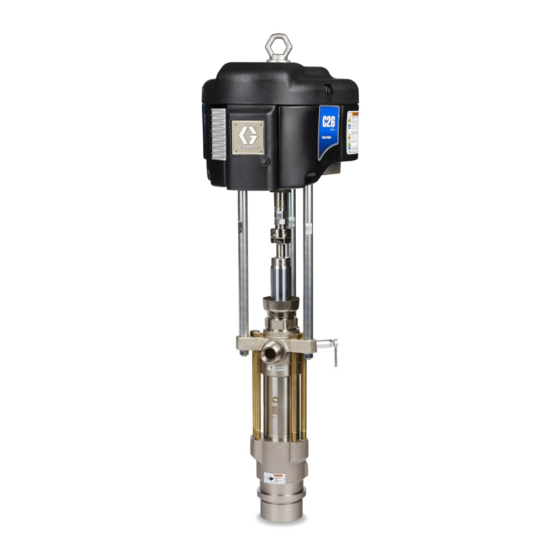
Instructions – Parts List
CARBON STEEL
Dura-Flot 1800 Pumps
With Severe–Duty Rod and Cylinder
Important Safety Instructions
Read all warnings and instructions in this manual.
Save these instructions.
See page 2 for List of Models and Table of
Contents.
Part No. 222837 Shown
308147Y
ENG
Advertisement

Related Manuals for Graco Dura-Flo 1800 Series


Summary of Contents for Graco Dura-Flo 1800 Series
- Page 1 Instructions – Parts List CARBON STEEL 308147Y Dura-Flot 1800 Pumps With Severe–Duty Rod and Cylinder Important Safety Instructions Read all warnings and instructions in this manual. Save these instructions. See page 2 for List of Models and Table of Contents. Part No.
- Page 2 ........Graco Information ..... . .
- Page 3 D Read all instruction manuals, tags, and labels before operating the equipment. D Use the equipment only for its intended purpose. If you are not sure, call your Graco distributor. D Do not alter or modify this equipment. Use only genuine Graco parts and accessories.
- Page 4 WARNING SKIN INJECTION HAZARD Spray from the gun, leaks or ruptured components can inject fluid into your body and cause extremely serious injury, including the need for amputation. Fluid splashed in the eyes or on the skin can also cause serious injury. D Fluid injected into the skin might look like just a cut, but it is a serious injury.
- Page 5 WARNING FIRE AND EXPLOSION HAZARD Improper grounding, poor ventilation, open flames or sparks can cause a hazardous condition and result in a fire or explosion and serious injury. D Ground the equipment and the object being sprayed. Refer to Grounding on page 6. D If there is any static sparking or you feel an electric shock while using this equipment, stop spray- ing immediately.
- Page 6 Installation (ALL PUMPS) Grounding 1. King Pumps: use a ground wire and clamp. See Fig. 1. Remove the ground screw (Z) and insert through eye of ring terminal at the end of ground WARNING wire (Y). Fasten ground screw back onto pump and tighten securely.
- Page 7 Notes 308147...
- Page 8 Fig. 3 is only a guide for selecting and installing sys- Pumps, assemble the displacement pump (105) to the tem components and accessories. Contact your Graco Premier air motor (101) as instructed on page 18. distributor for assistance in designing a system to suit your particular needs.
- Page 9 Installation (AIR-POWERED PUMPS) SYSTEM ACCESSORIES Air Line Accessories Install the following accessories in the order shown in Fig. 3, using adapters as necessary: WARNING An air line lubricator (D) provides automatic air A bleed-type master air valve (E) and a fluid drain motor lubrication.
- Page 10 It is very important to keep the hydraulic supply system clean at all times. Be sure that all hydraulic NOTE: Accessories are available from your Graco fluid lines are absolutely clean. Blow out the lines distributor. If you supply your own accessories, be sure...
- Page 11 Carefully follow the manufacturer’s recommendations Fluid Line Accessories on reservoir and filter cleaning, and periodic changes of hydraulic fluid. Use only Graco-approved hydraulic Install the following accessories in the positions shown oil. Order Part No. 169236, 5 gal. (19 liter) or 207428, in Fig.
- Page 12 Operation/Maintenance (ALL PUMPS) Pressure Relief Procedure Packing Nut/Wet-Cup Fill the packing nut/wet-cup (3) 1/3 full with Graco WARNING Throat Seal Liquid (TSL) or compatible solvent. See Fig. 5. Using the supplied wrench (104), adjust the packing nut weekly so it is just snug; do not overtigh- SKIN INJECTION HAZARD ten.
- Page 13 Operation/Maintenance (AIR-POWERED PUMPS) Starting and Adjusting the Pump 6. Use the air regulator to control the pump speed and the fluid pressure. Always use the lowest air pressure necessary to get the desired results. 1. Refer to Fig. 3 on page 8. Connect the suction kit Higher pressures cause premature tip/nozzle and (T) to the pump’s fluid inlet, and place the tube into pump wear.
- Page 14 Operation/Maintenance (HYDRAULIC-POWERED PUMPS) Starting and Adjusting the Pump 9. With the pump and lines primed, and with ade- quate hydraulic volume supplied, the pump will 1. Refer to Fig. 4 on page 10. Connect the suction kit start and stop as the gun/valve is opened and (T) to the pump’s fluid inlet, and place the tube into closed.
- Page 15 Operation/Maintenance (HYDRAULIC-POWERED PUMPS) Shutdown and Care of the Pump Always flush the pump before the fluid dries on the displacement rod. Never leave water or water-based WARNING fluid in the pump overnight. First, flush with water or a compatible solvent, then with mineral spirits. Relieve the pressure, but leave the mineral spirits in the pump To reduce the risk of serious injury whenever you to protect the parts from corrosion.
- Page 16 Troubleshooting Chart 1. Relieve the pressure. WARNING 2. Check all possible causes and problems before To reduce the risk of serious injury whenever you disassembling the pump. are instructed to relieve pressure, always follow the Pressure Relief Procedure on page 12. PROBLEM CAUSE SOLUTION...
- Page 17 Service Required Tools WARNING Set of socket wrenches Set of adjustable wrenches For Model 222939 Premier Pump, do not lift the 24 in. adjustable wrench pump by the lift ring when the total weight exceeds Torque wrench 550 lb (250 kg). Rubber mallet Arbor press 3.
- Page 18 Fill the wet-cup (3) 1/3 full of 1. Screw the connecting rod adapter (102) to the air Graco Throat Seal Liquid or compatible solvent. motor shaft. Torque as specified in Fig. 6. 9. Turn on the air or hydraulic power supply. On 2.
- Page 19 Service King, Bulldog, and Viscount Pumps Premier Pumps (Model 222837 Shown) (Model 237555 Shown) 0567C 01397C Torque to 129–142 N m (95–105 ft-lb) Torque to 196–210 N m (145–155 ft-lb) Torque to 312–340 N m (230–250 ft-lb) Torque to 135–169 N m (100–125 ft-lb) Apply LoctiteR 2760t (or equivalent) to threads.
- Page 20 Service DISPLACEMENT PUMP SERVICE 7. Stand the cylinder (7) upright on a wooden block. Using a rubber mallet or an arbor press, drive the Disassembly displacement rod (1) and piston assembly down into the cylinder as far as possible, then place the When disassembling the pump, lay out all the removed cylinder on its side and continue to drive the rod parts in sequence, to ease reassembly.
- Page 21 Service 0421B Fig. 7 308147...
- Page 22 Service Reassembly 5. Lubricate the o-ring (27*) and seal (6*). Install the o-ring on the intake seat housing (15). Install the 1. If it was necessary to remove the ball guide (9) intake seat housing (15), intake ball (16), ball guide from the displacement rod (1), place the flats of (14), and seal (6*) in the intake housing (17).
- Page 23 Service Torque to 156–171 NSm (115–126 ft-lb). Torque to 135–169 NSm (100–125 ft-lb). Torque to 459–481 NSm (338–354 ft-lb). Torque oppositely and evenly to 244–264 NSm (180–195 ft-lb). Apply anti-seize lubricant to threads and mating faces. Lubricate. Apply thread lubricant. Use arbor press to drive into cylinder (7).
- Page 24 Parts Part No. 222837 Pump, Series A 28:1 Ratio, with King Air Motor Ref. Part No. Description Qty. 245111 AIR MOTOR, King See 309347 for parts 102} 184451 ADAPTER, connecting rod 103} 184096 NUT, coupling 184278 WRENCH, packing nut 222796 PUMP, displacement See pages 28 &...
- Page 25 Parts Part No. 222891 Pump, Series B 28:1 Ratio, with Quiet King Air Motor Ref. Part No. Description Qty. 220106 AIR MOTOR, King, quiet See 309348 for parts 102} 184451 ADAPTER, connecting rod 103} 184096 NUT, coupling 184278 WRENCH, packing nut 222796 PUMP, displacement See pages 28 &...
- Page 26 Parts Part No. 237555 Pump, Series B Part No. 233127* Pump, Series A 45:1 Ratio, with Premier Air Motor 45:1 Ratio, with Premier Air Motor Part No. 241490 Pump, Series A Part No. 233128* Pump, Series A 45:1 Ratio, with Premier Air Motor 45:1 Ratio, with Premier Air Motor Ref.
- Page 27 Parts Part No. 222892 Pump, Series B with Viscount Hydraulic Motor Ref. Part No. Description Qty. 235345 HYDRAULIC MOTOR, Viscount See 307158 for parts 102} 184595 ADAPTER, connecting rod 103} 184096 NUT, coupling 184278 WRENCH, packing nut 222796 PUMP, displacement See pages 28 &...
- Page 28 Parts NOTE: The parts listed on this page are common to all Part displacement pumps covered in this manual. The pumps use Description different packing configurations. Standard Model 222805 uses stainless steel cap screws with washers. Optional 184276 ROD, displacement; stainless steel pumps use carbon steel cap screws without a washer.
- Page 29 Parts Standard Displacement Pump Displacement Pump 222796, Series A (PTFE and Leather Packings) THROAT PACKINGS: PISTON PACKINGS: Part LIPS FACE DOWN LIPS FACE UP Description 184232 GLAND, male; piston; stainless steel 184312 V-PACKING; piston; leather 184181 GLAND, female; throat; stainless steel 1 109311 V-PACKING;...
- Page 30 Packing Conversion Kits Packing Conversion Kit 222845, Packing Conversion Kit 222848, (UHMWPE and PTFE Packings) (UHMWPE and Leather Packings) THROAT PACKINGS: PISTON PACKINGS: THROAT PACKINGS: PISTON PACKINGS: LIPS FACE DOWN LIPS FACE UP LIPS FACE DOWN LIPS FACE UP 0805 0805 LUBRICATE PACKINGS 0806...
- Page 31 Notes 308147...
- Page 32 Technical Data Sound Level Data* Pump Model Air Pressure Cycle Rate Sound Pressure Level Sound Power level 222837 90 psi 25 cycles/min 98 dB(A) 113 dB(A) 222891 90 psi 25 cycles/min 86.2 dB(A) 101 dB(A) 237555 77 psi 25 cycles/min 88 dB(A) 103 dB(A) 233127...
- Page 33 Technical Data (MODELS 222837 AND 222891 KING PUMPS) WARNING Be sure that all fluids and solvents used are chemically compatible with the Wetted Parts listed below. Always read the manufacturer’s literature before us- ing fluid or solvent in this pump. Ratio .
- Page 34 Technical Data (MODELS 237555, 233127, and 233128 PREMIER PUMP) WARNING Be sure that all fluids and solvents used are chemically compatible with the Wetted Parts listed below. Always read the manufacturer’s literature before us- ing fluid or solvent in this pump. Ratio .
- Page 35 Technical Data (MODEL 222892 VISCOUNT PUMP) WARNING Be sure that all fluids and solvents used are chemically compatible with the Wetted Parts listed below. Always read the manufacturer’s literature before us- ing fluid or solvent in this pump. Maximum fluid working pressure .
- Page 36 Dimensions Model 222837 Shown 0566 Pump Model 222837 1225.6 mm (48.25 in.) 642.6 mm (25.3 in.) 583.0 mm (22.95 in.) 298.0 mm (11.73 in.) 222891 1235.1 mm (48.63 in.) 642.6 mm (25.3 in.) 592.5 mm (23.33 in.) 298.0 mm (11.73 in.) 237555 1160.0 mm (45.7 in.) 759.0 mm (29.9 in.)
- Page 37 Mounting Hole Layouts King, Bulldog, and Viscount Pumps 94.28 mm (3.712 in.) 101.6 mm 94.28 mm (4.0 in.) (3.712 in.) 50.8 mm (2.0 in.) 11.1 mm (0.437 in.) DIA (4) 88 mm (3.464 in.) 0653 Premier Pumps 135.0 mm 67.5 mm (5.3 in.) (2.7 in.) 116.9 mm...
- Page 38 With the exception of any special, extended, or limited warranty published by Graco, Graco will, for a period of twelve months from the date of sale, repair or replace any part of the equipment determined by Graco to be defective.
Need help?
Do you have a question about the Dura-Flo 1800 Series and is the answer not in the manual?
Questions and answers