Table of Contents
Advertisement
Quick Links
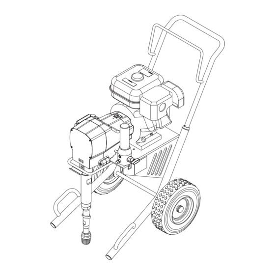
GPX 1250
G a s Pi s to n Pu m p
Printed in the U. S. A.
Model Number 0509005
Owner's Manual
SprayTECH
1770 Fernbrook Lane
Minneapolis, MN 55447
Technical Assistance: 1-800-292-4637
Order Entry: 1-800-443-4500
ww w.s pray t e chi nc . c o m
1202 © 2002 SprayTECH. All rights reserved. Form No. 0509812A
Fax: 1-800-525-9501
Advertisement
Table of Contents

Related Manuals for SprayTECH GPX 1250


Summary of Contents for SprayTECH GPX 1250
- Page 1 1770 Fernbrook Lane Minneapolis, MN 55447 Technical Assistance: 1-800-292-4637 Order Entry: 1-800-443-4500 Fax: 1-800-525-9501 ww w.s pray t e chi nc . c o m Printed in the U. S. A. 1202 © 2002 SprayTECH. All rights reserved. Form No. 0509812A...
-
Page 2: Table Of Contents
The maximum operating range of the gun is 3300 PSI / enclose a spray area. Do not use plastic drop cloths 228BAR fluid pressure. when spraying flammable materials. • Use lowest possible pressure to flush equipment. © SprayTECH. All rights reserved. - Page 3 • Wear clothing to keep paint off skin and hair. • Always unplug cord from outlet before working on equipment. • Do not use this equipment to spray water or acid. CAUTION Do not lift by cart handle when loading or unloading. © SprayTECH. All rights reserved.
-
Page 4: General Description
Refer to the engine manufacturer's service manual (supplied). 5. Move the engine ON/OFF switch to the ON position. 9. Close the fuel shut-off lever and fill the gas tank with gasoline. Use only high quality, unleaded gasoline. © SprayTECH. All rights reserved. -
Page 5: Painting
Open the fuel valve lever. NOTE: Turning the pressure up higher then needed to atomize the paint will cause premature tip wear b. Move the throttle lever away from the gas tank. and additional overspray. © SprayTECH. All rights reserved. -
Page 6: Pressure Relief Procedure
If the pressure is set too low, tailing will appear or the paint will spatter out in gobs rather than in a fine spray. Paint tailing pattern Do not flex wrist while spraying. © SprayTECH. All rights reserved. -
Page 7: Cleanup
4. If you have any further questions concerning your SprayTECH airless sprayer, call SprayTECH: 16. Continue to trigger the spray gun into the waste container until the solvent coming out of the gun is clean. -
Page 8: Maintaining The Engine
(Replacement elements can be purchased from your local SprayTECH dealer.) • After each 50 hours of operation: Change the engine oil. Spark Plug •... -
Page 9: Replacing The Potentiometer
WARNING Electrostatic discharge (ESD) potential could cause Electrostatic discharge (ESD) potential could cause damage to electronic pressure control. Use SprayTECH damage to electronic pressure control. Use SprayTECH ESD wrist strap P/N 0507958 or equivalent when working ESD wrist strap P/N 0507958 or equivalent when working on electronic pressure control. -
Page 10: Replacing The Transducer
EPC housing. Tighten securely. of the EPC housing. Disconnect this wire from the EPC 22. Take the sprayer to a SprayTECH Authorized Service board (it has a phone jack-style connector). Center for re-calibration. -
Page 11: Replacing The Slider Assembly And Slider Housing
Lubriplate 1242 grease (the slider cup is the area on the slider assembly where the connecting rod and slider housing join and pivot). 14. Insert the slider assembly into the bushing end of the slider housing. © SprayTECH. All rights reserved. -
Page 12: Replacing The Gears
Insert the gear assembly into the bore in the Housing pump housing, pinion end first. Clutch Gear Housing Housing 15. Generously coat both faces of each of the crankshaft Hex Screw Engine Shaft thrust washers with grease. © SprayTECH. All rights reserved. - Page 13 “bottoms out” within the housing. Do not pinch the clutch field wires during installation. Electrostatic discharge (ESD) potential could cause damage to electronic pressure control. Use SprayTECH NOTE: Apply blue Loctite to the four clutch field set ESD wrist strap P/N 0507958 or equivalent when working screws prior to installation.
-
Page 14: Servicing The Fluid Section
WARNING Electrostatic discharge (ESD) potential could cause Before proceeding, follow the Pressure Relief Procedure damage to electronic pressure control. Use SprayTECH outlined previously in this manual. Additionally, follow all ESD wrist strap P/N 0507958 or equivalent when working other warnings to reduce the risk of an injection injury, on electronic pressure control. - Page 15 “Operation” section of this manual and check for leaks. tighten. NOTE: Repacking kit P/N 0509510 is available. For Large Beveled Edge best results use all parts supplied in this kit. © SprayTECH. All rights reserved.
-
Page 16: Troubleshooting
1. Turn the pressure control knob clockwise to supply power to the unit and increase the pressure setting. 2. Faulty or loose wiring. 2. Inspect or take to a SprayTECH authorized service center. 3. The gas tank is empty. 3. Fill the gas tank. - Page 17 4. Add solvent to the material according to the viscous. manufacturer's recommendations. The unit lacks power. 1. The pressure adjustment is too low. 1. Rotate the pressure control knob clockwise to increase the pressure setting. © SprayTECH. All rights reserved.
-
Page 18: Français
• Tous les accessoires doivent être homologués pour une pression égale ou supérieure à 3 200 lb/po2 / 228BAR. Cela s'applique, entre autres, aux têtes de pulvérisation, aux accessoires du pistolet et aux flexibles. Français © SprayTECH. Tous droits réservés. - Page 19 à une pression égale ou supérieure à 3 200 lb/po2 / 228BAR. • Ne jamais pulvériser lorsqu'il vente. • Porter des vêtements pour protéger la peau et les cheveux contre tout contact avec la peinture. Français © SprayTECH. Tous droits réservés.
-
Page 20: Español
Consulte el manual del motor • Todos los accesorios deben tener una capacidad de 3300 para obtener información completa de seguridad. lb/pulg2 / 228BAR o mayor. Esto incluye las boquillas de atomizador, pistolas, extensiones y mangueras. Español © SprayTECH. Todos los derechos reservados. - Page 21 3300 lb/pulg2 / 228 BAR o mayor. • No atomice en días con viento. • Use ropa que evite el contacto de la pintura con la piel y el cabello. Español © SprayTECH. Todos los derechos reservados.
-
Page 22: Parts Listings
Cart assembly..........1 0509915 Front cover..........1 0509551 Lock nut ............4 0509552 Screw............4 0507786 Lock washer..........2 0509520 Connecting pin..........1 0507787 Hex screw ...........2 0509521 Retaining ring..........1 0509553 Screw............2 0509133 Fluid section assembly .......1 0509928 Grounding cable .........1 © SprayTECH. All rights reserved. -
Page 23: Drive Assembly
Drive shaft assembly ........1 0291329 Engine, 5.5 HP ...........1 0509572 Clutch field assembly........1 0509569 Hex screw ...........4 0507748 Cap .............1 0507786 Lock washer..........4 NOTE: All electrical work should be performed by a Spraytech authorized service center. © SprayTECH. All rights reserved. -
Page 24: Fluid Section Assembly
Lower packing insertion tool NOTE: When repacking the fluid section, make sure the raised lip on the bottom of the lower packing is fully outside the packing around the piston rod after insertion of the piston rod. © SprayTECH. All rights reserved. -
Page 25: Cart Assembly
Outlet fitting, 3/8” ........1 9885571 Plug.............2 0507738 Plug, 1/4” ............1 0295606 Lock washer..........4 0507793 Fitting, 1/4”..........1 0295608 Screw............4 0509522 Filter housing ..........1 0509575 Cart (includes item 9) .........1 0507690 PRIME/SPRAY valve assembly....1 0509624 Wheel ............2 © SprayTECH. All rights reserved. -
Page 26: Prime/Spray Assembly
Cam base ...........1 0089799 5006543 Groove pin ..........1 Engine 0507662 Valve handle ..........1 Labels Part # Description 0509516 Logo label, front 0295840 Warning label, explosion 0295841 Warning label, injection 0295805 Shock hazard label 0509819 “No Oil” label © SprayTECH. All rights reserved. -
Page 27: Accessories
G-10 Four Finger Spray Pack with 50’ x 1/4” airless hose 0502012 G-10 Two Finger Spray Pack with 50” x 1/4” Airless Hose 0279920 Separating oil 0507958 Electrostatic discharge (ESD) wrist strap 9870307 Grease, 6 lb. can © SprayTECH. All rights reserved. -
Page 28: Limited Warranty
SprayTECH’s option, refund to the original purchaser the full purchase price for the product in exchange for the return of that product. However, SprayTECH will not replace or repair any fluid pump component on account of wear more than once during the two year warranty period.
Need help?
Do you have a question about the GPX 1250 and is the answer not in the manual?
Questions and answers
Motor runs good but when cycling the pump it shuts down
The SprayTECH GPX 1250 pump could shut down when cycling due to issues such as a clogged pump filter, gun filter, or inlet screen, a worn or oversized spray tip, or an improperly set pressure control knob.
This answer is automatically generated
Is there a spray gun for SprayTECH GPX 1250
Yes, the G-10 Four Finger and Two Finger Airless Spray Guns listed are compatible with the SprayTECH GPX 1250.
This answer is automatically generated