Table of Contents
Advertisement
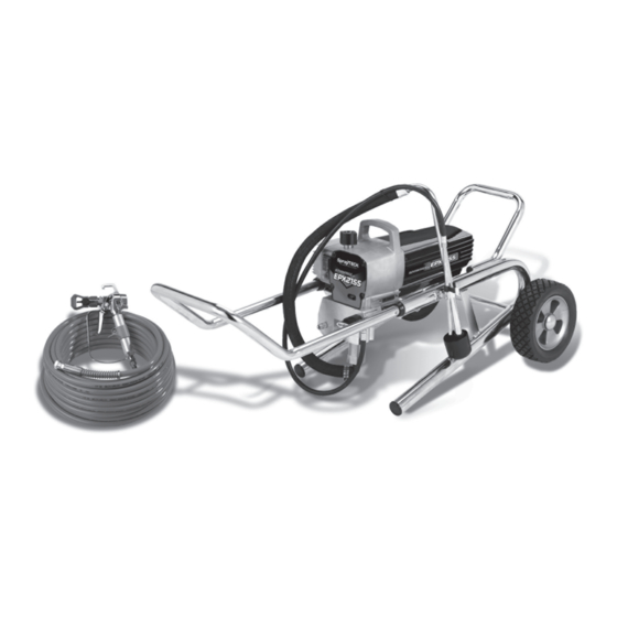
E PX2 1 5 5
Piston Pump
Printed in the U. S. A.
Model Numbers:
0551010 Stand
0551012 Upright Cart
0551013 Low Boy Cart
Owner's Manual
SprayTECH
1770 Fernbrook Lane
Minneapolis, MN 55447
Technical Assistance: 1-800-292-4637
Order Entry: 1-800-443-4500
ww w. spr ayt e c h in c .c om
1104 © 2004 SprayTECH. All rights reserved. Form No. 0551544A
Fax: 1-800-525-9501
Advertisement
Table of Contents

Related Manuals for SprayTECH EPX2155


Summary of Contents for SprayTECH EPX2155
- Page 1 1770 Fernbrook Lane Minneapolis, MN 55447 Technical Assistance: 1-800-292-4637 Order Entry: 1-800-443-4500 Fax: 1-800-525-9501 ww w. spr ayt e c h in c .c om Printed in the U. S. A. 1104 © 2004 SprayTECH. All rights reserved. Form No. 0551544A...
-
Page 2: Table Of Contents
Do not use plastic drop cloths when 20.7 MPa fluid pressure. spraying flammable materials. PREVENTION: • Use lowest possible pressure to flush equipment. • NEVER aim the gun at any part of the body. © SprayTECH. All rights reserved. -
Page 3: Specifications
Maximum hose length......300’ (91.4 m) • Do not spray outdoors on windy days. • Wear clothing to keep paint off skin and hair. • Always unplug cord from outlet before working on equipment. © SprayTECH. All rights reserved. -
Page 4: General Description
6. Allow the sprayer to run for 15–30 seconds to flush the old 8. Plug the power cord into a properly grounded outlet at solvent out through the return hose and into the metal least 25’ from the spray area. waste container. © SprayTECH. All rights reserved. -
Page 5: Painting
8. Remove the return hose from the waste container and lock to the locked position. place it in its operating position above the container of 8. Move the PRIME/SPRAY valve down to paint. the PRIME position. © SprayTECH. All rights reserved. -
Page 6: Spraying
The sprayer, hose, and gun should be cleaned thoroughly a stroke. This will result in an uneven spray and splotchy after daily use. Failure to do so permits material to build coverage. up, seriously affecting the performance of the unit. © SprayTECH. All rights reserved. -
Page 7: Cleaning The Spray Tip
Always contact the supplier of solvents for recommendations. WARNING 4. If you have any further questions concerning your SprayTECH Airless Sprayer, call SprayTECH: Ground the gun by holding it against Technical Service........1-800-292-4637 the edge of the metal container while Fax ..........1-800-525-9501... -
Page 8: Replacing The Filters
Heavy bodied latex, Coarse green Screw blockfillers, elastometrics Capacitors NOTE: For more detail, part number information, and an assembly drawing, please see the G-10 XL Motor Airless Spray Gun Owner's Manual (P/N Mounting 0296237). Screw Motor Cover © SprayTECH. All rights reserved. -
Page 9: Replacing The Motor Brushes
Connecting Pin Pump Motor Cover Manifold Retaining Ring Motor Cover Screw Motor Armature Gear Pump Manifold Crankshaft/Gear Mounting Assembly Screw Motor Mounting Screw Thrust Washer 2nd Stage Gear Gear Box Housing Front Cover Front Cover Screw © SprayTECH. All rights reserved. -
Page 10: Servicing The Fluid Section
6. Reassemble the valves by reversing the steps above. When the connecting pin hole on the piston rod lines up with the hole in the slider assembly, insert the connecting pin. 15. Slide the retaining ring down over the connecting pin. © SprayTECH. All rights reserved. - Page 11 21. Turn on the sprayer by following the procedure in the “Operation” section of this manual and check for leaks. NOTE: Repacking kit P/N 0551533 is available. For best results use all parts supplied in this kit. © SprayTECH. All rights reserved.
-
Page 12: Troubleshooting
4. Faulty or loose wiring. 4. Inspect or take to a SprayTECH authorized service center. 5. Excessive motor temperature. 5. Allow motor to cool. - Page 13 The unit lacks power. 1. The pressure adjustment is too low. 1. Rotate the pressure control knob clockwise to increase the pressure setting. 2. Improper voltage supply. 2. Reconnect the input voltage for 120V AC. © SprayTECH. All rights reserved.
- Page 14 • Tous les accessoires doivent être homologués pour une pression égale ou supérieure à 3000 lb/po2 / 20.7 MPa. Cela s'applique, entre autres, aux têtes de pulvérisation, aux accessoires du pistolet et aux flexibles. Français © SprayTECH. Tous droits réservés.
- Page 15 à une pression égale ou supérieure à 3000 lb/po2 / 20.7 MPa. • Ne jamais pulvériser lorsqu'il vente. • Porter des vêtements pour protéger la peau et les cheveux contre tout contact avec la peinture. Français © SprayTECH. Tous droits réservés.
- Page 16 Consulte el manual del motor • Todos los accesorios deben tener una capacidad de 3000 para obtener información completa de seguridad. lb/pulg2 / 20.7 MPa o mayor. Esto incluye las boquillas de atomizador, pistolas, extensiones y mangueras. Español © SprayTECH. Todos los derechos reservados.
- Page 17 3000 lb/pulg2 / 20.7 MPa o mayor. • No atomice en días con viento. • Use ropa que evite el contacto de la pintura con la piel y el cabello. Español © SprayTECH. Todos los derechos reservados.
-
Page 18: Parts List
Siphon tube (upright cart only) ....1 0551104 Suction set assembly 0551556 Return hose (upright cart only)....1 (stand and low boy cart) ......1 5006536 Inlet screen (upright cart only) ....1 9890212 Return hose clamp (not shown) ....1 © SprayTECH. All rights reserved. -
Page 19: Motor Assembly
PRIME/SPRAY knob label 0507856 PRIME/SPRAY label Item Part # Description Quantity 0551437 Siphon tube assembly ........1 0551439 Return hose ..........1 0279459 Hose clip .............1 0295565 Inlet screen ..........1 9871105 O-ring............2 9822526 Retaining ring..........1 9850638 Tie wrap ............2 © SprayTECH. All rights reserved. -
Page 20: Gear Box Assembly
Gear Box Assembly NOTE: All electrical work should be performed by a SprayTECH authorized service center. © SprayTECH. All rights reserved. -
Page 21: Stand Assembly
Screw............1 9890104 Cap .............2 0508381 Drip cup ............1 0294534 Spacer ............4 0551527 Screw............2 0278373 Wheel............2 0509856 Nut ..............1 0551525 Plug.............4 0551524 Right leg assembly (includes items 2, 4, 5, 6, 8, and 10) 0507955 Screw............1 © SprayTECH. All rights reserved. -
Page 22: Fluid Section Assembly
Piston assembly (includes items 9–13) ..1 0551533 Repacking kit (includes items 2–4, 8 10–11, 15, 17, and 19) 0551509 Lower seal insertion tool Raised Lip O-Ring Install lower packings with raised lip and O-ring facing up. © SprayTECH. All rights reserved. -
Page 23: Low Boy Cart Assembly
Drip cup ............1 0551551 Mounting bracket, left .........1 0551552 Mounting bracket, right .......1 Electrical Schematic NOTE: All electrical work should be performed by a SprayTECH authorized service center. Male/Female Piggyback P/N 0295418 Circuit P/N 0507974 Breaker 90º Female Quick Connect... -
Page 24: Accessories
Limited Warranty SprayTECH, a division of Wagner Spray Tech Corporation ("SprayTECH"), warrants that at the time of delivery to the original purchaser for use (“End User”), the equipment covered by this warranty is free from defects in material and workmanship. With the exception of any special, limited, or extended warranty published by SprayTECH, SprayTECH ’s obligation under this...
Need help?
Do you have a question about the EPX2155 and is the answer not in the manual?
Questions and answers