Table of Contents
Advertisement
Quick Links
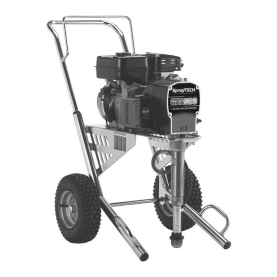
GPX 130
Gas Pis ton Pum p
Do not use this equipment before reading this manual!
NOTE: This manual contains important warnings and
instructions. Please read and retain for reference.
Printed in the U. S. A.
Model Numbers:
Bare
Complete
Bare w/5 Gal. Siphon
Complete w/5 Gal. SIphon
Owner's Manual
0509008
0509038
0509054
0509058
SprayTECH
1770 Fernbrook Lane
Minneapolis, MN 55447
Technical Assistance: 1-800-292-4637
Order Entry: 1-800-443-4500
ww w. sp ray t e c h in c .c o m
0306 © 2006 SprayTECH. All rights reserved. Form No. 0555881A
Fax: 1-800-525-9501
Advertisement
Table of Contents

Related Manuals for SprayTECH GPX 130


Summary of Contents for SprayTECH GPX 130
- Page 1 NOTE: This manual contains important warnings and instructions. Please read and retain for reference. ww w. sp ray t e c h in c .c o m Printed in the U. S. A. 0306 © 2006 SprayTECH. All rights reserved. Form No. 0555881A...
-
Page 2: Table Of Contents
Be familiar with the controls 2. Keep hands and other body parts away from the and the proper usage of the equipment. discharge. For example, do not try to stop leaks with any part of the body. © SprayTECH. All rights reserved. -
Page 3: Specifications
Occupational Safety and Health Act (OSHA). These standards, particularly part Weight ..........159 lbs. (72.1 kg) 1910 of the General Standards and part 1926 of the Maximum hose length......300’ (91.4 m) Construction Standards should be consulted. © SprayTECH. All rights reserved. -
Page 4: General Description
(supplied). when moving the PRIME/SPRAY valve to 9. Close the fuel shut-off lever and fill the gas tank with PRIME in case the sprayer is pressurized. gasoline. Use only high quality, unleaded gasoline. © SprayTECH. All rights reserved. -
Page 5: Painting
Move the throttle lever away from the gas tank. keep the pressure control knob at the lowest setting that maintains good atomization. NOTE: Turning the pressure up higher than needed to atomize the paint will cause premature tip wear and additional overspray. © SprayTECH. All rights reserved. -
Page 6: Pressure Relief Procedure
If the pressure is set too low, tailing will appear or the paint will spatter out in gobs rather than in a fine spray. Paint tailing pattern Do not flex wrist while spraying. © SprayTECH. All rights reserved. -
Page 7: Cleanup
Refer to the edge of the metal container while Troubleshooting section to help identify other possible flushing. Failure to do so may lead to a problems. static electric discharge, which may cause a fire. © SprayTECH. All rights reserved. -
Page 8: Maintaining The Engine
Replace the element if necessary. If operating in an unusually dusty environment, check the filter daily and replace if necessary. (Replacement elements can be purchased from your local SprayTECH dealer.) Gasket • After each 50 hours of operation: Change the engine oil. -
Page 9: Replacing The Potentiometer
WARNING Electrostatic discharge (ESD) potential could cause Electrostatic discharge (ESD) potential could cause damage to electronic pressure control. Use SprayTECH damage to electronic pressure control. Use SprayTECH ESD wrist strap P/N 0507958 or equivalent when working ESD wrist strap P/N 0507958 or equivalent when working on electronic pressure control. -
Page 10: Replacing The Transducer
3. Locate the transducer wire in the EPC housing. This wire the EPC housing. Tighten securely. will be protruding from a hole in the lower left hand corner 22. Take the sprayer to a SprayTECH Authorized Service of the EPC housing. Disconnect this wire from the EPC Center for re-calibration. -
Page 11: Replacing The Slider Assembly And Slider Housing
Lubriplate 3000W grease (the slider cup is the area on the slider assembly where the connecting rod and slider housing join and pivot). 14. Insert the slider assembly into the bushing end of the slider housing. © SprayTECH. All rights reserved. -
Page 12: Replacing The Gears
Insert the gear assembly into the bore in the Housing pump housing, pinion end first. Clutch Gear Housing Housing 15. Generously coat both faces of each of the crankshaft Hex Screw Engine Shaft thrust washers with grease. © SprayTECH. All rights reserved. - Page 13 4. Install the retaining ring into its groove next to the large ball bearing. Electrostatic discharge (ESD) potential could cause damage to electronic pressure control. Use SprayTECH ESD wrist strap P/N 0507958 or equivalent when working on electronic pressure control.
-
Page 14: Servicing The Fluid Section
Electrostatic discharge (ESD) potential could cause injury from moving parts or electric shock. damage to electronic pressure control. Use SprayTECH ESD wrist strap P/N 0507958 or equivalent when working 4. Remove the return hose from on electronic pressure control. - Page 15 Outlet Valve damaged, reverse to the unused Retainer side or replace the seat. 26. Clean and inspect the outlet cage and outlet valve ball. Replace if they are worn or damaged. © SprayTECH. All rights reserved.
- Page 16 54. Turn on the sprayer by following the procedure in the “Operation” section of this manual and check for leaks. NOTE: Repacking kit P/N 0509510 is available. For best results use all parts supplied in this kit. © SprayTECH. All rights reserved.
-
Page 17: Troubleshooting
1. Turn the pressure control knob clockwise to supply power to the unit and increase the pressure setting. 2. Faulty or loose wiring. 2. Inspect or take to a SprayTECH authorized service center. 3. The gas tank is empty. 3. Fill the gas tank. -
Page 18: Français
électriques reliées à la terre. être placée sur PRIME pour libérer la pression. Consultez N’utilisez pas d’adaptateur 3 à 2. la PROCÉDURE DE LIBÉRATION DE PRESSION décrite dans le manuel de la pompe. Français © SprayTECH. Tous droits réservés. - Page 19 Unis ont été adoptées dans la loi Occupational safety and Health Act (OSHA). Ces normes, en particulier la partie 1910 des Normes générales et la partie 1926 des Normes de construction, doivent être consultées. Français © SprayTECH. Tous droits réservés.
-
Page 20: Español
Inspeccione la manguera antes de cada uso. Sustituya compatibilidad con el aluminio. las mangueras o las piezas dañadas. Español © SprayTECH. Todos los derechos reservados. - Page 21 No repare nunca una manguera de pintura. Sustitúyala por una manguera conductora a alta presión. 13. No pulverice al aire libre si hace viento. 14. Desenchufe siempre el cable antes de trabajar en el equipo. Español © SprayTECH. Todos los derechos reservados.
-
Page 22: Parts Listings
Connecting pin..........1 0509553 Screw............2 0509521 Retaining ring..........1 0509928 Grounding cable .........1 0509133 Fluid section assembly .......1 0507785 Return hose (not shown) ......1 0509542 Siphon tube..........1 0507387 Hose, high pressure (not shown) ....1 0507783 Hose clip .............1 © SprayTECH. All rights reserved. -
Page 23: Drive Assembly
Clutch rotor ..........1 0509567 Drive shaft assembly ........1 0555617 Engine............1 0555902 Clutch field assembly........1 0509569 Hex screw ...........4 0507748 Cap .............1 0507786 Lock washer..........4 NOTE: All electrical work should be performed by a SprayTECH authorized service center. © SprayTECH. All rights reserved. -
Page 24: Fluid Section Assembly
Lower packing insertion tool NOTE: When repacking the fluid section, make sure the raised lip on the bottom of the lower packing is fully outside the packing around the piston rod after insertion of the piston rod. © SprayTECH. All rights reserved. -
Page 25: Cart Assembly
0555218 Cart (includes item 10) .......1 0507737 Transducer..........1 0509624 Wheel ............2 0509420 Plug, 3/8” ............1 0509738 Outlet fitting, 3/8” ........1 0295697 Plug, 1/4” ............1 0507793 Fitting, 1/4”..........1 0555625 Filter housing ..........1 0507690 PRIME/SPRAY valve assembly....1 © SprayTECH. All rights reserved. -
Page 26: Prime/Spray Assembly
Return hose ..........1 0509185 Siphon hose..........1 5006536 Inlet screen ..........1 0507783 Clamp ............1 0509727 Swivel elbow ..........1 0509760 Adapter ............1 0509761 Hose clamp..........1 0509788 Clip..............1 0509789 Spring ............1 55 Gallon Siphon Set (optional, P/N 0507977) © SprayTECH. All rights reserved. -
Page 27: Electrical Schematic
Separating oil Part # Description 0507958 Electrostatic discharge (ESD) wrist strap 0555899 Logo label, front 9870307 Grease, 6 lb. can 0295840 Warning label, explosion 0295841 Warning label, injection 0295805 Shock hazard label 0509819 “No Oil” label © SprayTECH. All rights reserved. -
Page 28: Limited Warranty
Limited Warranty SprayTECH, a division of Wagner Spray Tech Corporation ("SprayTECH"), warrants that at the time of delivery to the original purchaser for use (“End User”), the equipment covered by this warranty is free from defects in material and workmanship. With the exception of any special, limited, or extended warranty published by SprayTECH, SprayTECH ’s obligation under this...
Need help?
Do you have a question about the GPX 130 and is the answer not in the manual?
Questions and answers