Table of Contents
Advertisement
Quick Links
E PX2 3 5 5
Piston Pump
Printed in the U. S. A.
Model Numbers:
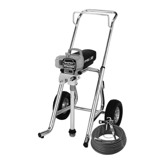
0551080 Upright Cart, Complete
0551090 Low Boy Cart, Complete
Owner's Manual
SprayTECH
1770 Fernbrook Lane
Minneapolis, MN 55447
Technical Assistance: 1-800-292-4637
Order Entry: 1-800-443-4500
ww w. spr ayt e c h in c .c om
1204 © 2004 SprayTECH. All rights reserved. Form No. 0551546A
Fax: 1-800-525-9501
Advertisement
Table of Contents

Related Manuals for SprayTECH EPX2355


Summary of Contents for SprayTECH EPX2355
- Page 1 1770 Fernbrook Lane Minneapolis, MN 55447 Technical Assistance: 1-800-292-4637 Order Entry: 1-800-443-4500 Fax: 1-800-525-9501 ww w. spr ayt e c h in c .c om Printed in the U. S. A. 1204 © 2004 SprayTECH. All rights reserved. Form No. 0551546A...
-
Page 2: Table Of Contents
• NEVER aim the gun at any part of the body. • NEVER allow any part of the body to touch the fluid stream. DO NOT allow body to touch a leak in the fluid hose. © SprayTECH. All rights reserved. -
Page 3: Specifications
Maximum hose length......300’ (91.4 m) • Do not spray outdoors on windy days. • Wear clothing to keep paint off skin and hair. • Always unplug cord from outlet before working on equipment. © SprayTECH. All rights reserved. -
Page 4: General Description
2. Place the return hose into a metal waste container. 7. Make sure the electrical service is 120V, 15 amp minimum. 8. Plug the power cord into a properly grounded outlet at least 25’ from the spray area. © SprayTECH. All rights reserved. -
Page 5: Painting
NOTE: Hold the return hose in the waste container when moving the PRIME/SPRAY valve to PRIME in case the sprayer is pressurized. 5. Turn on the sprayer by moving the ON/OFF switch to the ON position. © SprayTECH. All rights reserved. -
Page 6: Pressure Relief Procedure
If the pressure is set too low, tailing will appear or the paint will spatter out in gobs rather than in a fine spray. Paint tailing pattern Do not flex wrist while spraying. © SprayTECH. All rights reserved. -
Page 7: Cleanup
Always contact the supplier of solvents SPRAY position. for recommendations. 11. Turn on the sprayer. 4. If you have any further questions concerning your SprayTECH Airless Sprayer, call SprayTECH: WARNING Technical Service........1-800-292-4637 Fax ..........1-800-525-9501 Ground the gun by holding it against the edge of the metal container while flushing. -
Page 8: Replacing The Prime/Spray Valve
NOTE: The filter housing should be hand-tightened, but make sure the filter housing is seated fully into the pump manifold. Adapter Filter Support Spring Filter Seal Filter Housing Filter Spring Filter Pump Manifold © SprayTECH. All rights reserved. -
Page 9: Replacing The Motor Assembly
WARNING Electrostatic discharge (ESD) potential could cause Electrostatic discharge (ESD) potential could cause damage to electronic control. Use SprayTECH ESD wrist damage to electronic control. Use SprayTECH ESD wrist strap P/N 0507958 or equivalent when working on strap P/N 0507958 or equivalent when working on electronic control with electronic cover removed. -
Page 10: Replacing The Transducer
Pump 5. Remove, clean, and inspect the outlet valve cage and Manifold outlet valve ball. Replace if they are worn or damaged. Mounting 6. Reassemble the valves by reversing the steps above. Screw © SprayTECH. All rights reserved. - Page 11 14. Position the pump block underneath the pump housing and push up until it rests against the pump housing. When the connecting pin hole on the piston rod lines up with the hole in the slider assembly, insert the connecting pin. © SprayTECH. All rights reserved.
-
Page 12: Troubleshooting
4. Faulty or loose wiring. 4. Inspect or take to a SprayTECH authorized service center. 5. Excessive motor temperature. 5. Allow motor to cool. - Page 13 The unit lacks power. 1. The pressure adjustment is too low. 1. Rotate the pressure control knob clockwise to increase the pressure setting. 2. Improper voltage supply. 2. Reconnect the input voltage for 120V AC. © SprayTECH. All rights reserved.
- Page 14 • Tous les accessoires doivent être homologués pour une pression égale ou supérieure à 3100 lb/po2 / 21.4 MPa. Cela s'applique, entre autres, aux têtes de pulvérisation, aux accessoires du pistolet et aux flexibles. Français © SprayTECH. Tous droits réservés.
- Page 15 à une pression égale ou supérieure à 3100 lb/po2 / 21.4 MPa. • Ne jamais pulvériser lorsqu'il vente. • Porter des vêtements pour protéger la peau et les cheveux contre tout contact avec la peinture. Français © SprayTECH. Tous droits réservés.
- Page 16 Consulte el manual del motor • Todos los accesorios deben tener una capacidad de 3100 para obtener información completa de seguridad. lb/pulg2 / 21.4 MPa o mayor. Esto incluye las boquillas de atomizador, pistolas, extensiones y mangueras. Español © SprayTECH. Todos los derechos reservados.
- Page 17 3100 lb/pulg2 / 21.4 MPa o mayor. • No atomice en días con viento. • Use ropa que evite el contacto de la pintura con la piel y el cabello. Español © SprayTECH. Todos los derechos reservados.
-
Page 18: Parts List
Fluid section assembly (upright cart)..1 0508553 Screw............2 0551676 Fluid section assembly (low boy cart) 9890212 Return hose clamp (not shown) ....1 0551443 Pail hook (upright cart only)......1 0509636 Plug (low boy cart only, not shown)....2 © SprayTECH. All rights reserved. -
Page 19: Motor Assembly
0551473 Pressure control label Item Part # Description Quantity 0551437 Siphon tube assembly ........1 0551439 Return hose ..........1 0279459 Hose clip .............1 0295565 Inlet screen ..........1 9871105 O-ring............2 9822526 Retaining ring..........1 9850638 Tie wrap ............2 © SprayTECH. All rights reserved. -
Page 20: Gear Box Assembly
Gear Box Assembly NOTE: All electrical work should be performed by a SprayTECH authorized service center. © SprayTECH. All rights reserved. -
Page 21: Upright Cart Assembly
0278373 Wheel............2 0294534 Spacer ............4 0551550 Plug.............2 0551548 Plug.............2 13538 Bumper ............2 54458 Screw............2 0295606 Washer............4 0295608 Screw............4 0507774 Screw............4 0507655 Cord wrap ...........2 0551680 Cart weldment (includes items 8 and 9)..1 9890104 Cap .............2 © SprayTECH. All rights reserved. -
Page 22: Fluid Section Assembly
Filter assembly (includes items 22–27) ..1 Large Beveled Edge 0551677 Repacking kit (includes items 2, 3, 7, 9, 12, 16, 18, and 20) 0551511 Lower seal insertion tool Install lower packing with large beveled edge facing up. © SprayTECH. All rights reserved. -
Page 23: Low Boy Cart Assembly
Drip cup ............1 0551551 Mounting bracket, left .........1 0551552 Mounting bracket, right .......1 Electrical Schematic NOTE: All electrical work should be performed by a SprayTECH authorized service center. Power Cord WHITE MOTOR LEAD Potentiometer BLACK GREEN WHITE MOTOR LEAD WHITE... -
Page 24: Limited Warranty
Limited Warranty SprayTECH, a division of Wagner Spray Tech Corporation ("SprayTECH"), warrants that at the time of delivery to the original purchaser for use (“End User”), the equipment covered by this warranty is free from defects in material and workmanship. With the exception of any special, limited, or extended warranty published by SprayTECH, SprayTECH ’s obligation under this...
Need help?
Do you have a question about the EPX2355 and is the answer not in the manual?
Questions and answers