Table of Contents
Advertisement
Quick Links
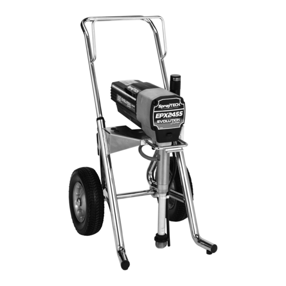
E PX2 4 5 5
Piston Pump
NOTE: This manual contains important warnings and
instructions. Please read and retain for reference.
Printed in the U. S. A.
Owner's Manual
Model Numbers:
0552060 Upright Cart Bare
0552065 Upright Cart Complete
0552070 Low Boy Cart Bare
0552075 Low Boy Cart Complete
SprayTECH
Technical Assistance: 1-800-292-4637
Order Entry: 1-800-443-4500
ww w. sp ray t e c h in c .c o m
0305 © 2005 SprayTECH. All rights reserved. Form No. 0551621A
1770 Fernbrook Lane
Minneapolis, MN 55447
Fax: 1-800-525-9501
Advertisement
Table of Contents

Subscribe to Our Youtube Channel
Related Manuals for SprayTECH EPX2455


Summary of Contents for SprayTECH EPX2455
- Page 1 NOTE: This manual contains important warnings and instructions. Please read and retain for reference. ww w. sp ray t e c h in c .c o m Printed in the U. S. A. 0305 © 2005 SprayTECH. All rights reserved. Form No. 0551621A...
-
Page 2: Table Of Contents
Avoid creating sparks from connecting and disconnecting power cords. 2. For units intended for use with only water-based materials — Do not spray or clean with flammable liquids. For use with water-based liquids only. © SprayTECH. All rights reserved. -
Page 3: Specifications
11. The United States Government Safety Standards have been adopted under the Occupational Safety and Health Act (OSHA). These standards, particularly part 1910 of the General Standards and part 1926 of the Construction Standards should be consulted. © SprayTECH. All rights reserved. -
Page 4: General Description
Operating this unit without fluid will cause unnecessary wear to the packings. 6. Make sure the electrical service is 120V, 15 amp minimum. 7. Plug the power cord into a properly grounded outlet at least 25’ from the spray area. © SprayTECH. All rights reserved. -
Page 5: Painting
6. Turn off the sprayer by moving the pressure control knob to the “0” position. 7. Remove the return hose from the waste container and place it in its operating position above the container of paint. © SprayTECH. All rights reserved. -
Page 6: Pressure Relief Procedure
5. Unlock the gun trigger lock. 6. Trigger the spray gun to bleed air out of the hose. 7. When paint reaches the spray tip, spray a test area to check the spray pattern. © SprayTECH. All rights reserved. -
Page 7: Unclogging The Spray Tip
If the sprayer does not pressure control knob to the “0” position. operate properly, review the repair procedure to determine if everything was done correctly. Refer to the Troubleshooting section to help identify other possible problems. © SprayTECH. All rights reserved. -
Page 8: Replacing The Prime/Spray Valve
2. Slip the filter off of the core 4. If you have any further questions concerning your Filter spring. SprayTECH Airless Sprayer, call SprayTECH: Body 3. Inspect the filter. Based on Technical Service........1-800-292-4637 inspection, clean or replace the Fax ..........1-800-525-9501... -
Page 9: Replacing The Motor Assembly (With Electronic Control)
17. Slide the motor shroud over the motor. Use only SprayTECH electronic cover screws to secure the electronic cover (see Drive Assembly parts list). Use of any 18. Secure the motor shroud with the four motor shroud other screws may damage the electronic control assembly. -
Page 10: Replacing The Transducer
18. Remove the upper packing assembly from the top of the cylinder. 19. Remove the adapter and lower packing assembly from the bottom of the cylinder. NOTE: Be careful not to scratch, score, or otherwise damage the cylinder during removal of the packings. © SprayTECH. All rights reserved. - Page 11 (beveled edge will be facing up when the cylinder is upright). © SprayTECH. All rights reserved.
-
Page 12: Troubleshooting
4. Faulty or loose wiring. 4. Inspect or take to a SprayTECH authorized service center. 5. Excessive motor temperature. 5. Allow motor to cool. - Page 13 The unit lacks power. 1. The pressure adjustment is too low. 1. Rotate the pressure control knob clockwise to increase the pressure setting. 2. Improper voltage supply. 2. Reconnect the input voltage for 120V AC. © SprayTECH. All rights reserved.
- Page 14 • Tous les accessoires doivent être homologués pour une pression égale ou supérieure à 3100 lb/po2 / 21.4 MPa. Cela s'applique, entre autres, aux têtes de pulvérisation, aux accessoires du pistolet et aux flexibles. Français © SprayTECH. Tous droits réservés.
- Page 15 à une pression égale ou supérieure à 3100 lb/po2 / 21.4 MPa. • Ne jamais pulvériser lorsqu'il vente. • Porter des vêtements pour protéger la peau et les cheveux contre tout contact avec la peinture. Français © SprayTECH. Tous droits réservés.
- Page 16 Consulte el manual del motor • Todos los accesorios deben tener una capacidad de 3100 para obtener información completa de seguridad. lb/pulg2 / 21.4 MPa o mayor. Esto incluye las boquillas de atomizador, pistolas, extensiones y mangueras. Español © SprayTECH. Todos los derechos reservados.
- Page 17 3100 lb/pulg2 / 21.4 MPa o mayor. • No atomice en días con viento. • Use ropa que evite el contacto de la pintura con la piel y el cabello. Español © SprayTECH. Todos los derechos reservados.
-
Page 18: Parts Listings
Filter assembly..........1 0507773 Jam nut ............1 0507690 PRIME/SPRAY valve assembly....1 0552155 Fluid section assembly ......1 5000527 Outlet fitting..........1 0507798 Siphon tube..........1 0507671 Fitting ............1 0507783 Hose clamp..........1 0507387 Hose (not shown) ........1 5006536 Inlet screen ..........1 © SprayTECH. All rights reserved. -
Page 19: Drive Assembly
Motor shroud..........1 9800340 Screw............1 0507961 Wire cover, 7” (not shown) ......1 0551624 Mounting plate ..........1 0507962 Wire assembly (not shown) ......1 0507757 Grommet.............1 NOTE: All electrical work should be performed by a Spraytech authorized service center. © SprayTECH. All rights reserved. -
Page 20: Fluid Section Assembly
0551687 Repacking kit (includes items 3, 5, 6, 8, 10, 11, 15, and 17–19) 0552150 Lower packing insertion tool Install lower packing so large beveled edge will be facing up when the cylinder is upright. © SprayTECH. All rights reserved. -
Page 21: Upright Cart Assembly
Plug.............2 0507984 Inner seal ............1 13538 Bumper ............2 0507690 PRIME/SPRAY valve assembly....1 54458 Screw............2 0295608 Screw............4 0507232 Transducer assembly (includes items 8–10) 0295606 Washer............4 0507774 Screw............4 0507655 Cord wrap ...........2 0507379 Wheel............2 9890104 Cap .............2 © SprayTECH. All rights reserved. -
Page 22: Suction Set Assembly (Low Boy)
Handle assembly 0294534 Wheel spacer..........4 (includes items 1–3, 5, 9, and 10) ....1 0278373 Wheel............2 0295610 Roll pin............2 9890104 Cap .............2 0295617 Plug.............2 ---------- Cart weldment (includes items 6 and 8)..1 0507955 Screw............1 5006854 Plug.............2 © SprayTECH. All rights reserved. -
Page 23: Electrical Schematic
Transducer Ground to Wire Assembly Gear Housing 0507962 ORANGE BLACK Potentiometer Assy Electronic Control Assy GREEN Motor BLACK WHITE Relay WHITE BLACK/RED/WHITE NOTE: All electrical work should be performed by a SprayTECH authorized service center. © SprayTECH. All rights reserved. -
Page 24: Limited Warranty
Limited Warranty SprayTECH, a division of Wagner Spray Tech Corporation ("SprayTECH"), warrants that at the time of delivery to the original purchaser for use (“End User”), the equipment covered by this warranty is free from defects in material and workmanship. With the exception of any special, limited, or extended warranty published by SprayTECH, SprayTECH ’s obligation under this...
Need help?
Do you have a question about the EPX2455 and is the answer not in the manual?
Questions and answers