Sign In
Upload
Download
Table of Contents
Contents
Add to my manuals
Delete from my manuals
Share
URL of this page:
HTML Link:
Bookmark this page
Add
Manual will be automatically added to "My Manuals"
Print this page
×
Bookmark added
×
Added to my manuals
Manuals
Brands
Owon Manuals
Measuring Instruments
HSA Series
User manual
Owon HSA Series User Manual
Handheld spectrum analyzer
Hide thumbs
1
2
3
Table Of Contents
4
5
6
7
8
9
10
11
12
13
14
15
16
17
18
19
20
21
22
23
24
25
26
27
28
29
30
31
32
33
34
35
36
37
38
39
40
41
42
43
44
45
46
47
48
49
50
51
52
53
54
55
56
57
58
59
60
61
62
63
64
65
66
67
68
69
70
71
72
73
74
75
76
77
78
79
80
81
82
83
84
85
86
page
of
86
Go
/
86
Contents
Table of Contents
Troubleshooting
Bookmarks
Table of Contents
Table of Contents
General Safety Requirements
Safety Terms and Symbols
Document Overview
Quick Start
General Inspection
Safety Precaution before Operation
First Time to Power on
Table 4-1 AC-DC Adapter Requirement
Front Panel Overview
Figure 4-1 Front Panel
Top Panel Overview
Figure 4-2 Top Panel
Rear Panel Overview
User Interface Overview
Figure 4-3 Rear Panel
Figure 4-4 User Interface
Function Keys
Figure 4-5 Function Softkeys
Figure 4-6 Shift Key and Function Hardkeys
Parameter Input
Figure 4-7 Numeric Keypad
Build-In Help
Figure 4-8 the Rotary Knob
Figure 4-9 Arrow Keys
Touchscreen Controls
Basic Measurement
Figure 4-10 Full Span
Figure 4-11 Set Frequency Span
Figure 4-12 Set Reference Level
Menu Interpretation
FREQ】 Bottom Softkey
Span】 Bottom Softkey
AMPTD】 Bottom Softkey
Auto】 Bottom Softkey
BW】 Bottom Softkey
Marker】 Bottom Softkey
Trace】 Hardkey
Detector】 Hardkey
Table 5-1 Detector Type Comparison
Display】 Hardkey
Sweep】 Hardkey
Trig】 Hardkey
Source】 Hardkey
Demod】 Hardkey
System】 Hardkey
Table 5-2 [Factory] Settings
File】 Hardkey
Measure】 Hardkey
Specification
Troubleshooting
Appendix
Appendix A: Enclosure
Appendix B: General Care and Cleaning
Appendix C: USB Disk Requirements
Appendix D: PC Software Requirements
Advertisement
Quick Links
Download this manual
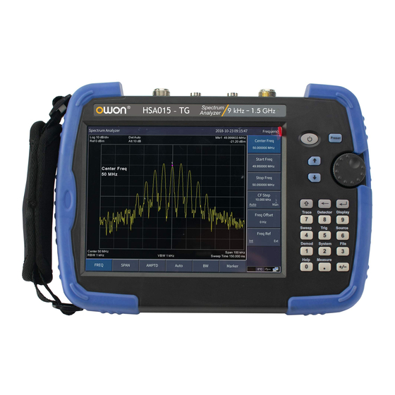
HSA Series
Handheld Spectrum Analyzer
User Manual
HSA015
HSA015-TG
HSA032
HSA032-TG
Notice: -TG models are with tracking generator
www.owon.com.cn
Table of
Contents
Previous
Page
Next
Page
1
2
3
4
5
Advertisement
Table of Contents
Need help?
Do you have a question about the HSA Series and is the answer not in the manual?
Ask a question
Questions and answers
Related Manuals for Owon HSA Series
Measuring Instruments Owon HSA1000 Series User Manual
Handheld spectrum analyzer (94 pages)
Measuring Instruments Owon HSA1000 Series User Manual
Handheld spectrum analyzer (86 pages)
Measuring Instruments Owon HDS1021M User Manual
Handheld digital storage oscilloscope & multimeter (64 pages)
Measuring Instruments Owon HDS2062M User Manual
Handheld digital storage oscilloscope & multimeter (73 pages)
Measuring Instruments Owon HSA1075 User Manual
Handheld spectrum analyzer (94 pages)
Measuring Instruments Owon HSA015 User Manual
Handheld spectrum analyzer (86 pages)
Measuring Instruments Owon HSA015-TG User Manual
Handheld spectrum analyzer (86 pages)
Measuring Instruments Owon HDS100 Series User Manual
Oscilloscope meter (43 pages)
Measuring Instruments Owon HSA2000 Dual Channel Series User Manual
Handheld spectrum (58 pages)
Measuring Instruments Owon CMS101 Manual
(17 pages)
Measuring Instruments Owon XSA1000 Series User Manual
Spectrum analyzer (79 pages)
Measuring Instruments Owon PC321-TY Quick Start Manual
Single/3-phase power clamp (16 pages)
Measuring Instruments Owon PC321 Quick Start Manual
Single/3-phase power clamp (10 pages)
Measuring Instruments Owon PC311-TY Quick Start Manual
Single-phase power clamp (20 pages)
Measuring Instruments Owon CM2100 User Manual
Ac/ dc clamp ammeter (39 pages)
Measuring Instruments Owon XSA800 Series User Manual
Spectrum analyzer (80 pages)
This manual is also suitable for:
Hsa015
Hsa015-tg
Hsa032
Hsa032-tg
Hsa1000 series
Table of Contents
Print
Rename the bookmark
Delete bookmark?
Delete from my manuals?
Login
Sign In
OR
Sign in with Facebook
Sign in with Google
Upload manual
Upload from disk
Upload from URL


Need help?
Do you have a question about the HSA Series and is the answer not in the manual?
Questions and answers