
Related Manuals for Owon XSA800 Series


Summary of Contents for Owon XSA800 Series
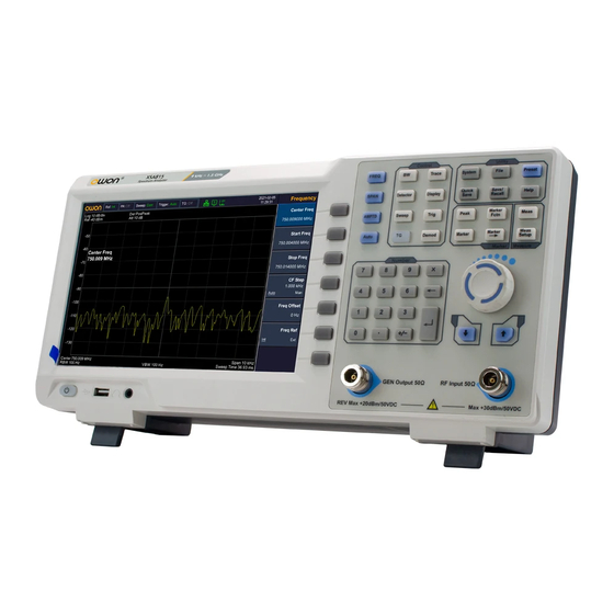
- Page 1 XSA800 Series Spectrum Analyzer User Manual ◼XSA805(TG) ◼XSA810(TG) ◼XSA815(TG) For product support, visit:www.owon.com.hk/download...
- Page 2 LILLIPUT Company. Fujian LILLIPUT Optoelectronics Technology Co., Ltd. No. 19, Heming Road Lantian Industrial Zone, Zhangzhou 363005 P.R. China Tel: +86-596-2130430 Fax: +86-596-2109272 Web: www.owon.com E-mail: info@owon.com.cn...
- Page 3 General Warranty We warrant that the product will be free from defects in materials and workmanship for a period of 3 years from the date of purchase of the product by the original purchaser from our company. The warranty period for accessories is 12 months.
-
Page 4: Table Of Contents
Table of Contents 1. General Safety Requirements..........1 2. Safety Terms and Symbols ............. 3 3. Document Overview............... 4 Related documents including: Quick guide, User manual, programme guide and etc............4 4. User Notice................5 General Inspection ................5 Safety Precaution before Operation ..........5 Check Power Supply ................ - Page 5 5.10 【Trig】 ................. 37 5.11 【TG】 ................... 38 5.12 【Demod】Demodulation ..........39 5.13 【Peak】................44 5.14 【Marker】 ................45 5.15 【Marker→】 ................ 48 5.16 【Marker Fctn】Marker Function ........49 5.17 【Meas】Measurement ............51 5.18 【Meas Setup】 ..............54 5.19 【System】 ................54 5.20 【File】...
-
Page 6: General Safety Requirements
1.General Safety Requirements 1. General Safety Requirements Before use, please read the following safety precautions to avoid any possible bodily injury and to prevent this product or any other connected products from damage. To avoid any contingent danger, ensure this product is only used within the ranges specified. - Page 7 1.General Safety Requirements ◼ Do not operate in an explosive atmosphere. In order to avoid damages to the device or personal injuries, it is important to operate the device away from an explosive atmosphere. ◼ Keep product surfaces clean and dry. To avoid the influence of dust or moisture in air, please keep the surface of device clean and dry.
-
Page 8: Safety Terms And Symbols
2.Safety Terms and Symbols 2. Safety Terms and Symbols Safety Terms Terms in this manual (The following terms may appear in this manual): WARNING Warning indicates conditions or practices that could result in injury or loss of life. CAUTION Caution indicates the conditions or practices that could result in damage to this product or other property. -
Page 9: Document Overview
3.Document Overview 3. Document Overview ⚫ Quick Start This chapter states the matters need to attention before first power on, how to power on at first time, introduces spectrum analyzer’s front/rear panel and user interface, explains how to use the instrument with a measurement example demonstration. -
Page 10: User Notice
4.User Notice 4. User Notice This chapter states the matters need to attention before first power on, and how to power on at first time, introduces spectrum analyzer’s front/rear panel and user interface, explains how to use the instrument with a measurement example demonstration. 4.1General Inspection When you receive your new instrument, it is recommended that you check the instrument following these steps:... -
Page 11: Allowed Variation Range Of Supply Power Parameters
4.User Notice cord. 4.2.2 Allowed Variation Range of Supply Power Parameters The spectrum analyzer is compatible with 100V~240V, 50Hz-60Hz AC power, Table 4-1 lists the power requirement to run the spectrum analyzer. Working Power Variation Range Table 4-1 Power Supply Parameter Compatible Range Voltage 100 - 240 VAC... -
Page 12: Electro-Static Discharge (Esd) Protection
4.User Notice WARNING Make sure the supply power is stable before turning on the analyzer to protect it from damage. Refer to "First Time to Power on" section 3. 4.2.4 Electro-static Discharge (ESD) Protection ESD is an issue often ignored by users. Damage from ESD on the instrument is unlikely to occur immediately but will significantly reduce the reliability of it. -
Page 13: Front Panel
4.User Notice WARNING Check the power source before turning on the spectrum analyzer, to protect the device from damage. 1) Press the power switch on the bottom left of the front panel. 2) Self-initialization takes about 30 seconds, after the boot screen the spectrum analyzer will default to the scanning curve. -
Page 14: Front Panel Function Key
4.User Notice Description Description ① ⑦ Numeric keypad ② ⑧ Menu softkeys Tracking generator output connector ③ Function keys ⑨ Earphone interface ④ ⑩ Knob USB Host port ⑤ Arrow keys ⑪ Power key (Push to turn on, long push to turn off) ⑥... - Page 15 4.User Notice Activates frequency sweep span function, and set Full Span\Zero Span\Last SPAN Span. Activates the reference level function, and accesses the amplitude softkeys, with AMPTD which you set functions that affect data on the vertical axis. Searches the signal automatically within the AUTO full frequency range.
- Page 16 4.User Notice Accesses the marker control keys that Marker select the type and number of markers and turns them on and off. Accesses the marker function softkeys that Marker allow you to set other system parameters based on the current marker value. Accesses the menu of special functions, Marker such as marker noise, N dB bandwidth...
-
Page 17: Parameter Input
4.User Notice 4.4.2 Parameter Input Specific parameter values are able to be entered using the numeric keypad, knob, and directional keys. Numeric Keypad Figure 4-3 Numeric Keypad 1. Numeric keys Numbers 0-9 are available to be used. Decimal point A decimal point "." will be inserted at the cursor position when this key is pressed. -
Page 18: Front Panel Connector
4.User Notice Figure 4-4 The knob The knob function: During parameter editing, turn the knob clockwise to increase, or counterclockwise to decrease the parameter values at specified steps. Direction key Figure 4-5 Direction keys The directional keys have following functions: 1) Increase or decrease the parameter value at specific steps while editing a parameter. -
Page 19: Rear Panel
4.User Notice CAUTION Input voltage at RF input port must not be higher than 50 V DC to avoid damage to the attenuator and input mixer tracking generator. 3. RF Input 50Ω The RF input may be connected to a device via a N type connector CAUTION When input attenuator is higher than 10 dB, the RF port input signal must be less than +30 dBm. - Page 20 4.User Notice ④ This configurable USB port permits USB Device external USB devices. It supports interface PictBridge printer and remote-control connection. ⑤ External trigger Connect an external TTL signal. connector ⑥ 10MHz The BNC input or output of the 10 MHz IN/OUT reference clock ⑦...
-
Page 21: User Interface
4.User Notice 4.6User Interface Figure 4-7 User interface Table 4-5 User interface Description Name Description Related Key Set the reference FREQ → [Freq Reference ① frequency as Int (internal) frequency Ref] or Ext (external) input Turn on/off the AMPTD→ ② Preamplifier preamplifier [Preamplifier]... - Page 22 4.User Notice Show the source type as CW (Continuous Wave) or 【TG】→ Tracking ⑤ TG (Tracking Generator), generator [Source GEN] press to turn on/off the source output access ⑥ LAN access sign sign 【 Demod 】 → Analog Turn on analog ⑦...
-
Page 23: Build-In Help
4.User Notice 【SPAN】 →[Span] or ㉑ Span Display span width 【FREQ】 →[Stop Freq] 【BW】→ Video ㉒ Display video bandwidth bandwidth [VBW] 【FREQ】→ Center ㉓ Display center frequency [Center Freq] or frequency [Start Freq] Resolution Display resolution ㉔ 【BW】 →[RBW] bandwidth bandwidth Display current activated ㉕... -
Page 24: Basic Measurement
4.User Notice 3.Close the current help information Press "Help" again to close help. 4.Acquire the menu help A message about how to obtain help information will be shown, press the menu keys to get the corresponding help. 5.Acquire the help information of any function key A message about how to obtain help information will be shown, press any function key to get the corresponding help. - Page 25 4.User Notice Figure 4-8 Full Span To clearly observe the signal, reduce the frequency span to 1 MHz and set the center frequency to 100MHz. 2) Setting Center Frequency Press "FREQ", select [Center frequency] on corresponding pop up menu. Input "100" and select the unit as MHz on the numeric keypad.
- Page 26 4.User Notice Figure 4-9 Set frequency span 4) Activate Marker —Press【Marker】button in the function area. Press the softkey to select [Marker 1 2 3 4 5 ], select Marker 1, the marker is located at horizontal center by default, that is the signal peak point or its neighbor.
- Page 27 4.User Notice Figure 4-10 Set reference level...
-
Page 28: Menu Interpretation
5.Menu Interpretation 5. Menu Interpretation This section provides you with the information on using the front panel of the spectrum analyzer. 5.1 【FREQ】Frequency The frequency range of a channel can be expressed by either of two groups of parameters: Start Frequency and Stop Frequency; or Center Frequency and Span. - Page 29 5.Menu Interpretation ⚫ The span and center frequency are changed automatically according to the start frequency. The change of the span would have influence on other system parameters. For more details, please refer to "Span". ⚫ In Zero Span mode, the start frequency, stop frequency and center frequency are always equal.
-
Page 30: Span
5.Menu Interpretation order to sweep the adjacent channels manually. ⚫ You can modify this parameter using the numeric keys, knob, or direction keys. Frequency step lends itself to detect the harmonic waves and bandwidths that are beyond the current span. For example, for order of harmonic of a 300 MHz signal, you can use set both the center frequency and frequency step to 300 MHz, and press the up direction key continuously to increase the... -
Page 31: Amptd】Amplitude
5.Menu Interpretation Sets the frequency range of the sweep. When pressed, the frequency mode is switched to Center Freq/Span. Key points: ⚫ The start and stop frequencies are changed with the span automatically. ⚫ In manual span mode, the span can be set down to 0 Hz, that is zero span mode. - Page 32 5.Menu Interpretation includes [Ref Level], [Attenuation Auto Manual], [Scale/Div], [Scale Type Lin Log], [Ref Offset], [Ref Unit], and [Preamplifier On Off]. 5.3.1 [Ref Level] Activate reference level function and sets the maximum power or voltage for display window. Key points: ⚫...
- Page 33 5.Menu Interpretation ⚫ Modifying the reference level may cause an automatic change in attenuation value; But the change of attenuation value won’t influence reference level. ⚫ You can modify this parameter using the numeric keys, knob, or direction keys. Attenuator adjustment is to make the maximum signal amplitude pass from mixer less than or equal to -10dBm.
- Page 34 5.Menu Interpretation Key points: ⚫ In Log scale type: the Y-axis denotes the logarithmic coordinates, the value shown at top of the grid is the reference level and the grid size is equal to the scale value. The unit of Y-axis will be automatically switched into the default "dBm"...
-
Page 35: Auto】Auto Tune
5.Menu Interpretation Choose decibel equals to 1μW as amplitude unit. Choose Watts as amplitude unit. Choose Voltage as amplitude unit. 5.3.7 [Preamplifier On Off] Sets the status of preamplifier located at the front of the RF signal path. Turning on the preamplifier reduces the displayed average noise level in order to distinguish small signals from the noise when working with small signals. - Page 36 5.Menu Interpretation resolution, but may also cause sweeps to take longer (Sweep Time is effected by a combination of RBW and VBW when it is in Auto mode). ⚫ RBW decreases with the span (non-zero span) in Auto RBW mode. 5.5.2 [RBW Mode Def Cont] Adjust resolution step mode, resolution mode can be set to 1-3-5, Default or Continuous mode.
-
Page 37: Trace
5.Menu Interpretation Set EMI measurement resolution to 120kHz. [9kHz] Set EMI measurement resolution to 9kHz. [200Hz] Set EMI measurement resolution to 200Hz. [Return] Return to the previous menu 5.6 【Trace】 As the sweep signal is displayed as a trace on the screen, you can set parameters about the trace using this key. -
Page 38: Detector
5.Menu Interpretation Stops updating trace data and display current trace for observation.. 5.6.7 [Operations►] Enter trace math related sub menu. 1) [1 ↔ 2] Exchange the trace stock 1 data with trace stock 2 and place them in display mode. 2) [2-DL →... - Page 39 5.Menu Interpretation ⚫ When 【BW/AVG】→[EMI Filter►]→[EMI Filter] is On, [Quasi-Peak] is available. Table 8-1 Detector type comparison Detector Measurement Type Pos Peak Positive peak detector ensures that no peak signal is missed, which is useful for measuring signals that are very close to the base noise.
-
Page 40: Display
5.Menu Interpretation Searches the minimum from the sampling data segment and displays it at the corresponding pixel. 5.7.3 [Normal] When noise is detected, the positive and negative peaks are alternately displayed, otherwise only positive peaks are displayed. 5.7.4 [Sample] Set the detector to the sampling detector mode. This mode is usually used for video averaging and noise frequency Maker. -
Page 41: Sweep
5.Menu Interpretation 5.8.2 [Zoom On Off] In multi-window display mode, press this button to zoom in on the selected window. Press the key for the first time to enlarge the selected window to the entire graphic display area. Press this button again to exit the entire graphic display area and restore the multi-window display mode. -
Page 42: Trig
5.Menu Interpretation ⚫ In non-zero span, the analyzer uses the shortest sweep time on the basis of the current RBW and VBW settings if Auto is selected. ⚫ You can modify this parameter using the numeric keys, knob, or direction keys. 5.9.2 [Sweep Mode Fast ACCY] Set the sweep mode of the spectrum analyzer to fast sweep or precise sweep. - Page 43 5.Menu Interpretation 5.10.3[External ►] In this mode, an external signal (TTL signal) is input from the [Trigger In] connector at the rear panel, its edge conditions should meet with the user settings to generate trigger signals. Press [External ►] to enter the submenu, and select [Positive Edge] or [Negative Edge] as the trigger condition.
-
Page 44: Demod】Demodulation
5.Menu Interpretation Tracking source network measurement function, mainly for amplitude and frequency characteristics measurement; RF output and spectrum measurement is fully synchronized, can be used as a scalar network analyzer. When the network measurement function is "on", the measurement results show relative values after "normalized", expressed in "dB". - Page 45 5.Menu Interpretation 5.12.1 [DEMOD►] Enter Audio Demod soft menu. 5.12.1.1 [Demod On Off] Turn audio demodulation on or off. 5.12.1.2 [Demod Mode►] Enter the demodulation mode soft menu. Including FM, AM. 5.12.1.3 [Sound] When the audio demodulation is on, adjust the speaker output volume.
- Page 46 5.Menu Interpretation Set the time axis, depth axis and AF trigger of AM modulation. 1) [Time Axis►] Set the time axis parameters. ⚫ [Ref.Value] Set the starting reference time on the time axis. ⚫[Position] Set the reference position of the waveform on the time axis. ⚫...
- Page 47 5.Menu Interpretation Set the triggering mode to single trigger or continuously trigger. ⚫[Trigger Level] Set the trigger level as a percentage of the depth. ⚫ [Trigger Delay] Set the trigger delay time. ⚫[Return] Return to the previous menu. 5.12.2.2 [FM►] Enter FM demodulation soft menu.
- Page 48 5.Menu Interpretation Automatically or manually set the grid division scale. ⚫[Return] Return to the previous menu. 2)[Deviation Axis►] Set the deviation axis parameters. ⚫[Ref Deviation] Set the reference offset position as a vertical percentage. ⚫[Position] Set the reference position of the waveform on the deviation axis. ⚫...
-
Page 49: Peak
5.Menu Interpretation 5.13 【Peak】 Executes peak searching immediately and opens the Peak setting menu. Key Points: ⚫ If Max is selected from the Peak Search option, it will search and mark the maximum on the trace. ⚫ The peak search of Next Peak, Peak Right, Peak Left or peaks in the peak table must meet the specified parameter condition. -
Page 50: Marker
5.Menu Interpretation Searches the peak with the minimum amplitude on the trace and identifies it with a marker. 5.13.6 [Mkr→CF] Used to move the peak point to the center frequency point. 5.13.7 [Cont Max On Off] Set the peak search form, off by default. On mode will automatically search for the peak. - Page 51 5.Menu Interpretation sweep width is 0Hz), and these values are displayed in the upper right corner of the active function area and the screen. You can use the numeric keys, the step key, or the knob to move the active frequency scale.
- Page 52 5.Menu Interpretation single marker already exists, [Delta] will place a static marker and an active marker to the original position and a single marker position. Use the knob, step key, or number keys to move the marker. If there are two markers, press [Delta] directly. However, if [Delta] has been activated, press [Delta] to place the still frequency scale to the active marker.
-
Page 53: Marker
5.Menu Interpretation Turns on or off the display of all marker table. 5.15 【Marker→】 A soft menu associated with the marker function is popped out for setting the other system parameters (such as Center frequency, Reference level) by current marker readings. These menus relate to the frequency of the spectrum analyzer, whether the sweep width and marker are in normal or delta marker mode. -
Page 54: Marker Fctn】Marker Function
5.Menu Interpretation frequency at which the Delta Marker is located. ⚫ The function is invalid in Zero span mode. 5.15.4 [Mkr->Stop] Sets the stop frequency of the analyzer based on the frequency of the current marker. ⚫ If Normal is selected, the stop frequency will be set to the frequency of the current marker. - Page 55 5.Menu Interpretation located on both sides of the current marker while the amplitude falls off (N<0) or rises (N>0) N dB separately, Key points: ⚫ When the measurement starts, the analyzer will search the two points which are located at both sides of the current point and are N dB amplitudes smaller or greater than the current point, and display the frequency difference between the two points.
-
Page 56: Meas】Measurement
5.Menu Interpretation 5.17 【Meas】Measurement Provide a variety of advanced measurement functions, pop-up spectrum analyzer built-in and user-defined measurement function soft menu, turn on or off the time spectrum, adjacent channel power measurement, channel power measurement, occupied bandwidth, Pass-Fail measurement menu. 5.17.1 [Measure off] You can directly close the currently running measurement function, you can also choose to close the measurement menu. - Page 57 5.Menu Interpretation 5.17.5 [OBW On Off] Turn on or off the occupied bandwidth measurement. Press 【Meas Setup】 to pop up the parameter setting soft menu for occupying the bandwidth measurement. Occupied Bandwidth is a measure of the bandwidth occupied by the transmitter signal can be measured from the total power ratio within the in-band power span, with a default value of 99% (the user can set this value).
- Page 58 5.Menu Interpretation frequency line is scanned. The peripheral stops scanning; the full frequency is scanned when it is closed. [Return] Return to the previous menu. 5.17.6.2 [Limit Meas►] Enter limit measurement soft menu. [Limit Meas On Off] Turn on or off limit measurement mode. [Line Up On Off] When the upper limit line is turned on or off, the upper limit line is opened by default when the area measurement is on.
-
Page 59: Meas Setup
5.Menu Interpretation 5.18 【Meas Setup】 Measurement setting menu for the corresponding measurement parameter settings when adjacent channel power, channel power, occupied bandwidth measurement mode is turned on. 5.18.1 [Channel BW] Set the bandwidth of the channel power measurement, and set the total display power percentage of bandwidth. - Page 60 5.Menu Interpretation Pop up system information and system log soft menu. [System Info] [Firmware Update] [Option] 5.19.1.1[System Info] Press to display system information. 5.19.1.2 [Firmware Update] 1. Create a folder named “spectrum” (lowercase) on the root directory of the USB memory device, and copy the firmware file onto this folder.
- Page 61 5.Menu Interpretation 5.19.2.1[LAN►] Pop out the relative menu for network configuring. [IP] Used to set the IP address of the LAN port. [Mask] Set the subnet mask parameter. [Gate] Set default gateway address. [DHCP On Off] One of the setting methods of IP address. The DHCP server assigns an IP address, subnet mask and gateway to the analyzer on the basis of the current network status.
- Page 62 5.Menu Interpretation 5.19.3 [PowerOn/Preset►] Used to set the analyzer power on parameters or reset parameters. 5.19.3.1 [Power Set►] Power-on parameter settings include [Factory],[User]and [Last]. 5.19.3.2 [Preset►] Power-on parameter settings include [Factory],[User]and [Last]. Note: To save the current system configuration as a user-defined configuration, press the [Save/Recall] panel key and select the [User Status] menu item.
- Page 63 5.Menu Interpretation Scale/div 10.00 dB Scale Type Reference Offset 0.00 dB Unit Preamp Resolution Bandwidth Auto 1 MHz Resolution Step Default Video Bandwidth Auto 1 MHz Trace Average Detector Detect Type Pos Peak Sweep Sweep Time Auto 24.000 ms Sweep Term Continuous Sweep Source Tracking Source...
- Page 64 5.Menu Interpretation Peak Search Marker Fctn Marker Noise Frequency Count Marker Marker Trace Marker List Meas Time Spectrum Adjacent Power Channel Power Occupied Bandwidth pass-fail Meas Setup Channel Bandwidth 1.000000 MHz Channel Gap 2.000000 MHz Adjacent Number Occupied Bandwidth 99.00% System Interface 192.168.1.13...
-
Page 65: File
5.Menu Interpretation [Factory]: If you do not need the user calibration compensation data, press the [Factory] key to clear the data and return to the factory status. 5.20 【File】 Pop up file management soft menu. 5.20.1 [Refresh] In the directory state, view the latest stored files. 5.20.2 [Type ►] To check file type under directory, includes screen image, trace data and display all. -
Page 66: Preset
5.Menu Interpretation 5.21 【Preset】 Press the [Preset] key on the front panel to restore the factory default settings or user-defined settings with one key. By default, the factory default settings [Preset] are restored with the 5.22 【Help】 Spectrum analyzer help menu, press this key once to open the system help, press any key to display the help content, and press this key again to close the help function. - Page 67 5.Menu Interpretation configuration. Save it in local. The information on saving the user status will display in the status bar of the bottom left corner of the screen. 5.23.2 [Recall►] Recall screenshot, trace data, user state or all related information. [Type►] 5.23.2.1 Select to recall screenshot, trace data, user state or all file types to...
-
Page 68: Quick/Save
5.Menu Interpretation [Trace Data] 5.23.3.2 Set the file type for quick save as trace data. [User Stage] 5.23.3.3 Set the file type for quick save as user state. 5.24 【Quick/Save】 Shortcut key for saving screenshots, trace data or user state. The type of file is set in the [Save Setup►] menu of the [Save/Recall] key. -
Page 69: Specification
6.Specification 6. Specification This chapter lists the technical specifications and general technical specifications of the spectrum analyzer. Unless otherwise stated, the technical specifications apply to the following conditions: ⚫The instrument has been preheated for 30 minutes before use. ⚫ The instrument is in the calibration cycle and has been self-calibrated. - Page 70 6.Specification ± (frequency indication × reference frequency Marker frequency accuracy + 1% × span + 10% × resolution uncertainty bandwidth + marker frequency resolution) Frequency Counter Resolution 1 Hz, 10 Hz, 100 Hz, 1 kHz ± (frequency indication × reference frequency Uncertainty accuracy + counter resolution) Frequency Span...
- Page 71 6.Specification DANL to +10 dBm, 100 kHz to 10MHz, Preamp Amplitude measurement DANL to +20 dBm, 10 MHz to 1.5 GHz, Preamp range Reference Level -80 dBm to +30 dBm, 0.1dBm by step Preamp 20 dB, nominal, 100 kHz to 1.5 GHz XSA805(TG)...
- Page 72 6.Specification quasi-peak clear write, max hold, min hold, average, Trace functions view, blank, trace math dBm, dBμW, dBpW, dBmV, dBμV, W, V Units of level axis Frequency response (20℃ to 30℃, 30% to 70% relative humidity, input attenuation=10 dB, reference frequency=50 MHz) Preamp Off ±...
- Page 73 6.Specification 95% confidence level, S/N > 20 dB, RBW = VBW = 1 kHz, preamplifier off, attenuation = Uncertainty 10 dB, -50 dBm < input level ≤ 0 dBm, fc > 10 MHz, 20℃ to 30℃ RF Input VSWR (attenuation ≥ 10 dB) 300 kHz to <1.5 (nominal) VSWR...
- Page 74 6.Specification span ≥ 100 Hz: 5% (nominal) Sweep time zero span (sweep time setting value > 1 ms): uncertainty 5% (nominal) Sweep Mode Continuous, Single Trigger Trigger source free run, video, external External trigger level 5 V TTL level Tracking Generator (Option) XSA805(TG)...
- Page 75 6.Specification frequency 10 MHz output level +3 dBm to +10 dBm, +8 dBm (typical) 50 Ω, typical Impedance Connector BNC female External reference frequency 10 MHz ± 5 ppm output level 0 dBm to + 10 dBm 50 Ω, typical Impedance Connector BNC female...
- Page 76 6.Specification Mass Memory Flash disk (internal storage 256 MByte), USB Mass memory storage device (not supplied) Power Supply Input voltage range, 100 V to 240 V AC supply frequency 50 Hz to 60 Hz Power consumption 28 W (nominal) Temperature 0 ℃...
-
Page 77: Warranty
7.Warranty 7. Warranty Troubleshooting Typical issues that may occur when using your spectrum analyzer: ◼ Power on malfunction ◼ No signal display ◼ Wrong measurement results or poor frequency or amplitude precision. 1. Power on malfunction Power on malfunction can include a situation where the screen is still dark (no display) after switch on. -
Page 78: Spectrum Analyzer Repair
7.Warranty If signal amplitude readout is not precise, perform a calibration. If amplitude readout is still not precise, then it may be a problem with internal circuit, please contact us for service. Spectrum Analyzer Repair When it is difficult to solve your spectrum analyzer’s problem, you can contact us by phone or fax. -
Page 79: Appendix
8.Appendix 8. Appendix Appendix A: Enclosure (The accessories subject to final delivery.) Standard Accessories Power Cord Quick Guide USB Cable Options N-SMA SMA-SMA SMA Adaptor N-SMA N-N Cable Cable Cable Adaptor Near Field Probe includes: Four near-field probes, N-SMA adapter, SMA-SMA cable ( Frequency range: 30 MHz –... -
Page 80: Appendix C: Usb Disk Requirements
8.Appendix require. To clean the instrument exterior, perform the following steps: Wipe the dust from the instrument surface with a soft cloth. Take care not to scratch the transparent LCD protection screen when cleaning. WARNING Before re applying power, ensure that the instrument is completely dry, avoiding any electric shock or electrical short circuit resulting from moisture.
Need help?
Do you have a question about the XSA800 Series and is the answer not in the manual?
Questions and answers