
Subscribe to Our Youtube Channel
Related Manuals for Owon CM2100


Summary of Contents for Owon CM2100
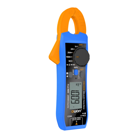
- Page 1 AC/ DC Clamp Ammeter User Manual CM2100 CM2100B For product support, visit:www.owon.com.hk/download...
- Page 2 LILLIPUT Company. Fujian LILLIPUT Optoelectronics Technology Co., Ltd. No. 19, Heming Road Lantian Industrial Zone, Zhangzhou 363005 P.R. China Tel: +86-596-2130430 Fax: +86-596-2109272 info@owon.com.cn Web: www.owon.com.cn E-mail:...
-
Page 3: Table Of Contents
Table of Contents I. Basic Overview ......................1 II. General Inspection ....................1 III. Safety Information ....................1 Safety Considerations ..................1 Measurement Category ..................3 Safety Terms and Symbols ................3 IV. Product Panel Diagram ..................4 V. LCD Full-Display Diagram ................... 5 VI. -
Page 4: Basic Overview
I. Basic Overview CM2100 AC/ DC clamp ammeter is characterized by high reliability, high safety, high accuracy and small size. Its resolution reaches 1mA and the maximum range is 100A AC\DC. This product has unique VFC start-up mode and can accurately measure the voltage and current of VFC after entering the mode;... - Page 5 Limit operation to the specified measurement category, voltage, or amperage ratings. Do not use the clamp ammeter if it is damaged. Before you use the clamp ammeter, inspect the case. Look for cracks or missing plastic. Pay particular attention to the insulation surrounding the connectors.
-
Page 6: Measurement Category
Connect the common test lead before you connect the live test lead. When you disconnect the leads, disconnect the live test lead first. Before changing functions, disconnect the test leads from the circuit under test. Measurement Category The clamp ammeter has a safety rating of 1000 V, CAT III and 600 V, CAT IV. Measurement category definition Measurement CAT I applies to measurements performed on circuits not directly connected to the AC mains. -
Page 7: Product Panel Diagram
Direct current (DC) Fuse Caution, risk of danger (refer to this Alternating current (AC) manual for specific Warning or Caution information) Both direct and alternating current Category II overvoltage protection Ground terminal Category III overvoltage protection Conforms to European Union Category IV overvoltage protection directives Equipment protected throughout by... -
Page 8: Lcd Full-Display Diagram
3. Clamp head trigger: Press the trigger to open the clamp head. 4. ZERO button: It is used for making DCA to zero, relative capacitance/voltage measurement/ press and hold the button for about 2 seconds to enable/ disable Bluetooth. 5. HOLD/ Backlight Button: It is used for locking measured reading / press and hold the button for about 2 seconds to enable/ disable backlight. -
Page 9: Operation Instructions
Select diode test Select continuity test Prompt of variable frequency voltage/ current measurement Measurement unit of temperature, ℃/ ℉ Percentage: Select duty cycle measurement Measurement unit of voltage, current and capacitance Measurement unit of resistance and frequency Measured value display; if the measured value is out of range, "OL"... - Page 10 Figure 2. Measurement of AC/ DC Current (Figure 4 and 5) AC Current a. Select the current range (2A, 20A, 100A): Press SELECT/ V.F.C button to enable the AC current flow function. b. Select the current range (2A, 20A, 100A): Press SELECT/ V.F.C button to enable the DC current flow function, and press the ZERO key before measurement to make the reading zero value.
- Page 11 Figure 4 Figure 5 3. Non-Contact Electric Field Measurement and Setting (Figure 6) If you need to measure whether there is an AC voltage in the space, please select the NCV function and keep the NCV antenna at the front end of the instrument clamp head close to the measured object at a distance of about 8-15mm for induction detection.
- Page 12 Figure 6 4. Resistance / Circuit ON/OFF/ Diode/ Capacitance Select resistance/ continuity /capacitance/diode function. Insert the red probe into the red hole (positive pole) and the black probe into the black hole (COM terminal). Connect the probes to the tested part for measurement (Figure 7) ...
- Page 13 (COM terminal). Get the red and black probes to contact the tested part, such as power socket (Figure 8). Read the measured data from the LCD screen. Figure 8 6. Other Functions Press and hold the HOLD button for about 2 seconds to turn on or off LCD backlight function. ...
-
Page 14: To Connect With Mobile Device
Please use your mobile device to scan the QR code below, click the APP installation package, download and install it. For iPhone You can search "OWON iMeter" on Apple Store, click the icon to obtain the APP installation package, download and install it. -
Page 15: How To Connect With Mobile Device
Note: The following help contents may not be completely consistent with the latest APP and be for reference only. The latest version of the User’s Manual can be obtained from our website. How to Connect with Mobile Device (1) Download and install the free AC/DC clamp ammeter APP on the mobile device. (2) Enable Bluetooth on the mobile device, and open the "AC/DC clamp ammeter"... -
Page 16: User Interface
(7) You can also filter out and select the required AC/DC clamp ammeter by opening the "Filter device". (8) After selecting the device, click it to enter the List of Devices. User Interface Please click the desired device in the List of Devices before entering the use interface of AC/DC clamp ammeter, as shown in the figure below:... -
Page 17: App Related Operations
Function Table Code Function Code Function DIODE Diode measurement CONT Continuity test Non-contact voltage Frequency measurement measurement Resistance DUTY Duty cycle measurement measurement Capacitance measurement APP Related Operations Device List Add AC/DC clamp ammeter: Click soft key in the device list. ... - Page 18 1. The user can customize the display name of the AC/DC clamp ammeter on the current device. Click icon in the top right corner of the view interface. 2. Go to the “More Settings“ interface. 3. Click "Modify device name" button. 4.
- Page 19 5. Click icon in the upper right corner of the interface to save the device name modified. Voice broadcast: Click icon in the upper left corner of the single view interface or click icon in the upper right corner to enter More Settings interface and enable or disable voice broadcast function.
- Page 20 3. Click it to enable "Threshold Alarm". 4. Click to set the required values and modes of "Upper limit, Lower limit and Alarm mode" (within range & outside range)
- Page 21 Offline Recording Function of AC/ DC Clamp Ammeter When the AC/DC clamp ammeter is used for measurement, the device APP sends a command to enable offline recording function of AC/DC clamp ammeter. After receiving the command, the AC/DC clamp ammeter is automatically disconnected, and can automatically save the measurement data in the storage area of the instrument under offline state.
- Page 22 (3) In the "Start to record" interface, set the record interval and the record counts. The record counts can be set to a maximum of 10,000. After setting, click "Start to record" button. Only the single off-line recorded data can be stored in the storage area of the AC/DC clamp ammeter. Therefore, when the recording begins, the last off-line record data stored in the AC/DC clamp ammeter will be overwritten.
- Page 23 Note: When the AC/DC clamp ammeter is in the data recording state but the recording has not been completed, if you connect the Android device to the AC/DC clamp ammeter at this time, the following selection box will pop up: ...
- Page 24 (6) In the off-line record reading interface, click "Save as: XXX" button. (7) Offline data files can be named. (8) Click "Read data" button to read the measurement data through the APP and save it in the zip format.
- Page 25 (9) After reading the data, click "Display data" button.
- Page 26 (10) The data display interface is shown as follows: Real-Time Data Real-Time Data Click Real-Time Data button to enter the real-time data interface.
- Page 27 Read File Click Read File button to enter the document reading interface.
- Page 28 2. Click “Open File” button. 3. Enter “Local File” interface. 4. Select the desired data file (offline data file & real-time data file) according to the need; take "real-time data file" for an example, the operation steps are shown as follows: a.
- Page 29 b. Enter the real-time data file interface and click the required data file. c. Enter the data file editing interface, and perform the following operations on the data file: Load data, Share, Rename, Remove and Cancel.
- Page 30 Function Setting 1. Click Function Setting button to enter the function setting interface.
- Page 31 2. Setting Data Chart record interval a. After the interval time of each data is set in the real-time data interface, the data shall be refreshed and recorded in real-time data interface according to the set interval time; b. Click Data Chart record interval button and then set the recording interval time in the display box below (setting range: 1s~11h: 59m: 59s);...
- Page 32 3. Setting Data Chart record count a. Set the number of recorded data in the real-time recording interface, and then the data will be saved and displayed on the real-time recording interface according to the set number of records; b. Click Data Chart record count button, and set the number of real-time data records in the display box below (setting range: 100-3000);...
- Page 33 4. Auto save: The automatic storage function is to save the data of the real-time data interface according to a fixed period. If a device is being connected, the automatic storage function can be enabled, or else the automatic storage function cannot be enabled. Besides, the automatic storage function is automatically enabled when all the devices are disconnected.
- Page 34 d. Click Cancel button or click other part outside the setting box to cancel the current setting value. 6. Setting A few times a. The number of automatic storages can be set before the automatic storage function is enabled. After automatic storage is enabled, the real-time data storage task will be executed according to this set.
-
Page 35: Technical Specifications
7. Theme: Set the theme of the current device, Night theme or Day theme, and then click “Save” button. 8. About: Click this button to view the information about the instrument. 9. Exit: Click this button to quit the current APP. VIII. - Page 36 0.0001V 2.0000V VRMS frequency ±(0.8%+10dig) 0.001V 20.000V range: VFC mode± Voltage(V) 0.01V 200.00V 40Hz-1000 (4%+3) 0.1V 600.0V 0.001A 2.0000A ±(2%+8dig) 0.01A 20.000A Current(A) ±(2%+3dig) 0.1A 100.00A ±(3%+10dig) VRMS 2.0000A 0.001A VFC mode± frequency (4%+10) range: Current(A) 0.01A ±(2.5%+5dig) 20.000A 40Hz-1000 VFC mode±...
- Page 37 20.000MHz 0.001MHz 0.1%-99.9% (Typical ±(1.2%+3dig) Value:Vrms=1V,f= Duty Cycle(%) 0.1% 1kHz) 0.1%-99.9%(≥1kH ±(2.5%+3dig) [1]When selecting 2A small current measurement function, read the reading after the display value tends to be stable to ensure the accuracy of the value. [2]In capacitance measurement mode, if the range of 20.00mF is selected, the measurement time should last for more than 30 seconds.
-
Page 38: Care And Maintenance
Input Impedance ≥10MΩ √ Over-Range Warm CM2100 Without Bluetooth Communication CM2100B √ Battery 3V(1.5V×2)AAA Alkaline battery LCD Sizes 40mm*20mm Machine Weight 0.19kg Machine Dimensions 181.26mm*60.3mm*32mm Working Temperature 0℃~40℃ Storage Temperature -10℃~60℃ Relative Humidity ≤80% Operating: 3,000 meters Altitude Non-operating: 15,000 meters... -
Page 39: Appendix
1. Turn the power switch in the "OFF" position and remove the test probe from the input jack. 2. Unscrew a screw fixing the back cover of the battery with a screwdriver, remove the back cover of the battery, and then remove the old batteries as shown in the figure Replace them with 2 new batteries (specification: AAA1.5V) X.
Need help?
Do you have a question about the CM2100 and is the answer not in the manual?
Questions and answers