Table of Contents
Advertisement
Quick Links
Advertisement
Table of Contents

Related Manuals for Advantech B+B SMARTWORX ESWGP512 4SFP T


Summary of Contents for Advantech B+B SMARTWORX ESWGP512 4SFP T
- Page 1 ESWGP512‐4SFP‐T User Manual...
- Page 2 USA Headquarters Advantech B+B SmartWorx. 707 Dayton Road Ottawa, IL 61350 USA Phone (815) 433-5100 -- General Fax (815) 433-5105 Website: www.advantech-bb.com support@advantech-bb.com European Headquarters Advantech B+B SmartWorx Westlink Commercial Park Oranmore, Co. Galway, Ireland Phone +353 91-792444 -- Fax +353 91-792445...
-
Page 3: Table Of Contents
Power Input Connections ............................18 Web Browser Configuration ............................ 21 Basic settings ................................23 Advanced Settings ..............................28 port priority ................................30 Administration ................................47 Specifications ................................57 Standards and Certifications ............................58 Dimensional Drawing ..............................59 Advantech B+B SmartWorx Technical Support ......................61... -
Page 4: Figures
FIGURES Figure 1. Product Description ............................11 Figure 2.Fault Relay ..............................12 Figure 3.PoE DIP switch – Default setting shown (PoE enabled) ................. 13 Figure 4.Din Rail Mounting ............................15 Figure 5. Panel Mounting ............................15 Figure 6. Triangle Mark ..............................17 Figure 7. - Page 5 Figure 26.Static mode for PoE ............................. 29 Figure 27.Dynamic mode ............................. 30 Figure 28. Single Ring ..............................31 Figure 29.RingON Configuration ..........................31 Figure 30. Dual Ring ..............................32 Figure 31.Dual Ring Configuration ..........................32 Figure 32. Redundancy Setting/RSTP .......................... 33 Figure 33.Port information ............................
-
Page 6: Tables
Figure 53.PING Test results example ........................... 49 Figure 54.Email Alert settings ............................50 Figure 55.Relay Warning .............................. 51 Figure 56. Port packets monitor ..........................51 Figure 57. Sort function ............................... 52 Figure 58.MAC address list ............................53 Figure 59. Log info ............................... 53 Figure 60. -
Page 7: Radio Frequency Interference Statement
RADIO FREQUENCY INTERFERENCE STATEMENT This equipment has been tested and found to comply with the limits for a Class A computing device, pursuant to Part 15 of the FCC Rules. These limits are designed to provide reasonable protection against harmful interference when the equipment is operated in a commercial environment. This equipment generates, uses and can radiate radio frequency energy and, if not installed and used in accordance with the instruction manual, may cause harmful interference to radio communications. -
Page 8: Warranty
Products of other manufacturers sold by Advantech B+B SmartWorx are not subject to any warranty or indemnity offered by Advantech B+B SmartWorx, but may be subject to the warranties of the other manufacturers. Power supplies are limited to a six year warranty. -
Page 9: Contents Of Package
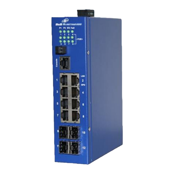
• Printed Quick Start Guide • 4-panel mounting clips with screws • RS-232 serial cable You may download the user manual at any time from the Advantech B+B SmartWorx web site: www.advantech-bb.com PRODUCT DESCRIPTION The ESWGP512-4SFP-T is a fully managed, full Gigabit PoE+ industrial switch, with eight (8) 802.3 af/at compliant Ethernet ports. -
Page 10: Features
FEATURES 10/100/1000Base-T Auto-Negotiation IEEE802.3af and IEEE802.3at, including two-event classification Supports legacy PD devices Managed, Plug and Play Full and Half Duplex Auto Cross feature for the RJ-45 copper port Eight 10/100/1000 copper POE+ ports ... -
Page 11: Hardware
HARDWARE Figure 1. Product Description... -
Page 12: Fault Relay
FAULT RELAY The Fault Relay can be enabled/disabled through the GUI. The Green LED is ON when the relay is closed. The Green LED is OFF when the relay is open. If the relay is set for "Break on Fault" and a port is set for "Warn when link is up", the LED is ON when link is detected, and OFF when link is broken. -
Page 13: Poe Reset
POE RESET Figure 3.PoE DIP switch – Default setting shown (PoE enabled) There are two PoE DIP Switches. One is for a Hardware Reset (HW RESET). The other is for an Auto Reset (AUTO RESET).By default, PoE is set to ON, and supplying PoE, Power over Ethernet. Hardware Reset: When the DIP Switch #1 is set to the ON position, the PoE function will be turned off, and the power sourcing for a PD device is unavailable. -
Page 14: Led Description
LED DESCRIPTION Device Face Status Description PWR (P1, P2) Green ON Power applied Green OFF No power Green Flashing System is UP, passing data Green ON/OFF System is DOWN Fault Green ON Relay closed Green OFF Relay open Console NO LED Connection for a CLI Using a hyperterminal program. -
Page 15: Din Rail Mounting
DIN RAIL MOUNTING The DIN Rail mounting clips are connected to the switch when shipped and ready to be mounted on a 35mm size DIN Rail. Figure 4.Din Rail Mounting PANEL MOUNTING Figure 5. Panel Mounting... -
Page 16: Rj-45 Ethernet Connection
RJ-45 ETHERNET CONNECTION All copper ports on the switch support the Auto Cross feature, which allows the end user to use a Straight-through or cross over cable. Each RJ-45 port provides PoE+ power simultaneously. PIN ASSIGNMENTS PIN# Signal Direction Description 10/100M PoE&PoE+ (ALT-A) Out*... -
Page 17: Sfp Installation And Connection
SFP INSTALLATION AND CONNECTION To connect the transceiver and fiber cable, follow the steps below. The SFP port is not proprietary. Any MSA-compliant 100Mbps fiber SFP can be installed in the port. (Note: SFP modules typically terminate with an LC fiber connector) First, insert the SFP transceiver into the SFP module cage. -
Page 18: Power Input Connections
POWER INPUT CONNECTIONS ESWGP512-4SFP-T accepts 44-57 VDC input voltage using terminal blocks. Figure 8. Power Input Connections Figure 9. Console mode NOTE: 1. The supplied RS-232 cable must be used. Straight through or cross over cable will not work. 2. If the Console screen does not appear select Enter. 1. -
Page 19: Figure 10. Login Screen
HyperTerminal configuration: • Serial baud rate: 115200 • Data Bits: 8 • Parity: NONE • Stop bits: 1 • Flow Control: NONE 3. If the Console screen does not appear, check the COM ports available on your system and the configuration settings. -
Page 20: Figure 11. Switch Status
• IP address: 192.168.118.100 • Subnet Mask: 255.255.255.0 • Gateway: 192.168.118.1 Figure 11. Switch status IP Settings The IP Settings page allows two methods of network address configuration, DHCP or Static. DHCP Setup • Use down arrow key to select IP Settings / select Enter •... -
Page 21: Web Browser Configuration
Factory Default The Factory Default page allows the managed switch to be set back to default settings. This will include the user name, password, and network settings. Figure 13. Factory default selection Logout When finished with viewing and configuring the settings in Console Mode. Move the arrow down to the Logout page and select Yes. -
Page 22: Figure 15. Browser Url
Figure 15. Browser URL The security login window will open requesting login user name and password. Defaults: • User Name: admin • Password: admin Figure 16.Logon screen for entering User Name, Password The browser will display the Overview page. The left column will display a list of configurable options. The Help button is at the top right. -
Page 23: Basic Settings
BASIC SETTINGS The following selections are available under Basic Settings: System Info Password Accessible IP Port Time System Information The System Information page allows the user to assign a unique name for the switch, the location of the switch, description of the switch, and contact name for the network administrator. -
Page 24: Figure 19. Configuration For User Name, Password, And User Index
Figure 19. Configuration for User Name, Password, and user index The maximum number of characters is 32 and a blank password can be configured. If a blank password is used the log file will not trace the login of this user. Accessible IP Two web server types are available, HTTP and HTTPS. -
Page 25: Figure 21.Port Configuration
The web server connection, HTTP (Hypertext Transfer Protocol), is a communications protocol used to transfer or convey information on the Internet using default port 80. Https is a URL that implements a Secure HTTP connection using default port 443. All entered access IP Addresses must be a legal IP address. Accessible IP addresses cannot be broadcast addresses or net mask (for example: 255.255.255.0). -
Page 26: Figure 23. Flow Control
Figure 23. Flow Control Setting Description Default value Media Type The type of media, copper or fiber Copper or Fiber Mode Auto Negotiation or FORCE mode settings Auto-Negotiation Flow Control Managing data transmission of packets Enable MDI/MDIX Medium dependent interface of nodes Auto MDI/MDIX Enable Enable port configuration options... -
Page 27: Figure 25. Time Settings
Table 4. IP Settings NOTE: Incorrect Subnet Mask configuration may cause erratic RingOn functionality. Time Setting Time Settings allows the user to select the appropriate Time Zone for the location. The NTP (Network Time Protocol) synchronizes the clocks of computer systems over packet-switched, variable-latency data networks. NTP uses UDP port 123 as its transport layer. -
Page 28: Advanced Settings
ADVANCED SETTINGS Under Advanced Settings, the following options are available: RingON VLAN Trunking IGMP Snooping GMRP Broadcast Storm Bandwidth Port Mirroring Static MAC address Forwarding Config. PoE Management Settings Supplying up to 30 watts of power per port, these PoE+ switches simplify the installation of powered devices (PD) such as IP CCTV, wireless access points, IP phones, and sensors. -
Page 29: Figure 26.Static Mode For Poe
Actual Power: Read only. Actual power of each port. Device Class: Read only. 0 – Class power for class 0, 1 – Class power for class 1, 2 – Class power for class 2, 3 – Class power for class 3, >=4 – Class power for class 4. ... -
Page 30: Port Priority
Figure 27.Dynamic mode PORT PRIORITY There are three levels of power priority: Low, Middle and High. The priority is used in the case where the remote devices require more power specified in “Power Supply Max” (this value is specific to the power supply being used). -
Page 31: Figure 28. Single Ring
Single RingOn configuration Figure 28. Single Ring The web configuration screen shot illustrates the steps needed to implement a single ring. In this case the switch is automatically configured as Master. Port 1 is used for communications and Port 2 is blocked. Only the master will display a Port Status of Blocked port. -
Page 32: Figure 30. Dual Ring
Figure 30. Dual Ring The web configuration screen shot illustrates the steps needed to implement a dual ring. Both ID 1 and 2 are enabled. Ports 1 and 2 connect single rings. Ports 3 and 4 connect the single rings together. Both rings are connected together using ID 4 coupling port. -
Page 33: Figure 32. Redundancy Setting/Rstp
Status and Port State definition Status Port State Default value Port 1 Fwd, Port 2 Fwd RingOn not enabled Complete Port 1 Fwd, Port 2 Block RingOn Master Complete Port 1 Fwd, Port 2 Fwd Ring Slave Incomplete Port 1 Fwd, Port 2 Down Port 2 RJ-45 link broken Incomplete Port 2 Down... -
Page 34: Figure 33.Port Information
Port Information under Port Configure Figure 33.Port information Port Configuration • Port Number • Priority: (0 - 240) A method of prioritizing how ports are blocked. The value is configured in multiples of 16 with the highest value being blocked. •... -
Page 35: Figure 34. Port Configuration
incurred by the port. The Auto setting will set the path cost as appropriate by the physical link speed, using the 802.1D recommended values. Using the Specific setting, a user-defined value can be entered. The path cost is used when establishing the active topology of the network. Lower path cost ports are chosen as forwarding ports in favor of higher path cost ports. -
Page 36: Figure 35. Rstp Root Bridge
Several VLANs may co-exist within such a network. VLANs help in reducing the broadcast domain and aids network administrators by separating logical segments of a LAN that should not exchange data. Advantech B+B SmartWorx managed switches support port-based VLANS and 802.1Q VLANS. -
Page 37: Figure 36.Tag/Untag Vlans
The illustration below shows the Tag Filter configured for both untagged and tagged port settings. Most PCs would be connected to a switch port that was configured for Un-tag. The two ports connecting the switches together are uplink ports and should be setup as Tag ports. Figure 36.Tag/Untag VLANs Figure 37. -
Page 38: Figure 38.Trunking Settings
Trunking Trunking, sometimes called Link Aggregation, is a method of paralleling more multiple ports between two switches. The ability to configure this type of connection will increase the speed beyond the limits of a single port. The multiple links between switches can also act as a redundant path if one port loses communication. -
Page 39: Figure 39.Qos Settings
DSCP Priority Settings High Queue Preemptive Mode Figure 39.QoS settings Port Priority • Two settings are available, Normal and High. When set to high, the packets have the lowest latency. 802.1p Priority The 802.1p header includes a three-bit field for prioritization, which allows packets to be grouped into various traffic classes. -
Page 40: Figure 41.Priority Settings
six used for delay-sensitive applications, four through one used in controlled data applications streaming data). The zero value is used as default (no other setting is uses). • 802.1p priority setting, assign tag of 0-7 (High, Middle, Low, Lowest) to each queue. Figure 41.Priority settings DiffServ Priority DiffServ or Differentiated Services is a computer networking architecture that specifies scalable and... -
Page 41: Figure 43.Dscp Settings
DSCP Priority Settings (Differentiated Services Code Point) DiffServ allows the administrator to configure how selected applications and types of traffic are handled by assigning various grades of network service to them. DSCP uses the IP header of a packet, and priority is then preserved across the Internet. -
Page 42: Figure 44.Igmp Settings
IGMP Snooping (Internet Group Management Protocol) IGMP Snooping provides a way to route multicast traffic and reduce unwanted traffic. IP multicasting is commonly used when sending the same information to many receivers. IGMP routes the multicast traffic to the correct devices and will not broadcast the message to unintended devices. IP multicast addresses are in the range of 224.0.0.0 through 239.255.255.255. -
Page 43: Figure 45. Gmrp
The length of the MAC address will remain in the multicast table. The switch will delete this group and send leave message. GMRP GMRP, GARP Multicast Registration Protocol, is a mechanism that allows bridges and switches to support a constrained multicast flooding of packets similar to IGMP snooping. It allows these devices to register and de-register attribute values, such as VLAN identifiers and multicast group membership. -
Page 44: Figure 46. Broadcast Storm Protection
Figure 46. Broadcast Storm Protection Max Bit Rate Max Bit Rate is a setting available if Broadcast Storm Protection is enabled. The bit rate setting can be adjusted between 65 Kbps and 90 Mbps or set to no limit. The storm protection feature will also allow the administrator to select the types of packets that are controlled. -
Page 45: Figure 47.Port Rate Settings
Figure 47.Port rate settings NOTE: I. The switch monitors all types of packets, but all packets have the same latency value. 2. The Switch will drop packets at a limited rate when flow control is disabled. Port Mirroring Port mirroring is used on a network switch to monitor the network traffic of a specific port. The selected port's Ethernet traffic is duplicated and sent out a second specified port. -
Page 46: Figure 49. Static Mac Address Settings
From Port: This is the source port -- data that is to be copied and monitored. To Port: This is the destination port -- data is received from the source port and analyzed. Data: Each port being monitored will transmit and receive data. During port mirroring the ingress data, egress data, or both can be mirrored to the selected port. -
Page 47: Administration
Note: 1. Defined MAC addresses assigned port can be modified. 2. Improper static unicast address may cause communication problems. 3. All static addresses can be found in MAC Address Table. 4. Do not add reserved addresses such as GMRP address to the address table. Reserved addresses are often used as managed address. -
Page 48: Figure 50.Snmp Settings
Figure 50.SNMP settings Diagnostics Scan Network and Ping are two diagnostic tools provided within the SNMP software. Scan Network will display a list of active network devices. The Ping function uses the PING command to give users a simple but powerful tool for troubleshooting network problems. Scan Network Scan Network will display IP address, MAC address, and its current status (active or Inactive). -
Page 49: Figure 52. Ping Test
Ping Test The Ping function implements the ping command to give users a simple but powerful tool for troubleshooting network problems. The function's most unique feature is that the PING command is entered from the user's PC, but the actual PING command originates from Managed switch itself. In this way, the user understands the LAN being tested. -
Page 50: Figure 54.Email Alert Settings
Alerts: Email Warning The Email Warning function allows e-mail alerts to be sent to defined users when port link (Up or Down) changes state, Relay Warning is enabled, Broadcast Storm events take place, and every 12 hours. The 12 hour report displays a log file of switch activities Figure 54.Email Alert settings Setting Description... -
Page 51: Figure 55.Relay Warning
Relay Warning The managed switch has a relay output that can be used to signal the occurrence of one or more events when configured by the user. Figure 55.Relay Warning Performance Monitor Performance monitoring is available for each port and displayed on the webpage. The data is captured and will display the total number of events that have occurred since last power cycle. -
Page 52: Figure 57. Sort Function
MAC Address Table MAC (Media Access Control) address is a hardware address that network devices are assigned by the manufacturer. The managed switch provides an 8K MAC address table with automatic learning and aging. The MAC address table displays this table only if the network administrator is logged on. In the address table, the MAC addresses can be sorted by specified type. -
Page 53: Figure 58.Mac Address List
Figure 58.MAC address list Log Information The Log Info page will display the Index (event number), Date of event, Time of event, Type, and Event description. A total of 16 messages can be displayed on each page. Each available page is selectable using the Page drop down menu. -
Page 54: Figure 60. Firmware Update
System Update Firmware Update To keep your managed switch up to date with the latest firmware, a field upgrade procedure is available. Perform the following steps to upgrade the firmware: 1. Download the updated firmware (*.img) file and place in a folder. 2. -
Page 55: Figure 61. Backup Settings
Backup Settings The managed switch’s configuration can be saved as a .cfg file and stored for later use. Select Download, then select Save. At that point you will be able to select a file location. NOTE: 1. The configuration file is saved with checksum. Do not edit this file. Figure 61. -
Page 56: Figure 62. Factory Default
Factory Default The Factory Default is used to restore the shipped default configuration. To restore, select "start" then "OK". Figure 62. Factory default It is recommended to save a current .cfg file before restoring default settings. -
Page 57: Specifications
SPECIFICATIONS Interfaces RJ45 Port 10/100/1000Base-T Auto-Negotiation, Full/Half Duplex, Auto-MDI/MDIX Fiber Ports 1000Base slot for MSA-compliant SFPs PoE+ Pinout V+, V+, V-, V-, for pin 1, 2, 3, 6 Alternative B Power Input Standard 4-pin dual power terminal blocks Connection Relay Output Standard 2-pin terminal blocks Console Port RJ45... -
Page 58: Standards And Certifications
STANDARDS AND CERTIFICATIONS IEEE Standards IEEE802.3af/at, 802.3, 802.3u, 802.3ab, 802.3z, 802.3x, 802.1w, 802.1Q, 802.1p, 802.1D Processing Type Store and Forward MAC Address Packet Buffer Size 512KB Jumbo Frame Size Store and Forward Broadcast Storm Automatic Broadcast Control Control Flow Control Full Duplex Flow Control, Half Duplex Back Pressure Control Jumbo Frame Size... -
Page 59: Dimensional Drawing
DIMENSIONAL DRAWING Figure 63. Dimensional drawing... - Page 60 The products described here in comply with the Council Directive on Electromagnetic Compatibility (2004/108/EC) and the Council Directive on Electrical Equipment Designed for use within Certain Voltage Limits (2006/95/EC). Will be certified for Information Technology Equipment including Electrical Business Equipment (Pending). European Directive 2002/96/EC (WEEE) requires that any equipment that bears this symbol on product or packaging must not be disposed of with unsorted municipal waste.
-
Page 61: Advantech B+B Smartworx Technical Support
ADVANTECH B+B SMARTWORX TECHNICAL SUPPORT Phone: 1-800-346-3119 (Monday - Friday, 7 AM. to 5:30 PM. CST) Fax: 815-433-5109 Email: support@advantech-bb.com Web: www.advantech-bb.com...
Need help?
Do you have a question about the B+B SMARTWORX ESWGP512 4SFP T and is the answer not in the manual?
Questions and answers